
Datasheet


TMP512
TMP513
SBOS491A –JUNE 2010– REVISED MAY 2011
www.ti.com
HIGH-SPEED MODE SENSOR FAULT
In order for the two-wire bus to operate at frequencies The TMP512/13 can sense an open circuit.
above 400kHz, the master device must issue a Short-circuit conditions return a value of –256°C. The
High-Speed mode (Hs-mode) master code (0000 detection circuitry consists of a voltage comparator
1xxx) as the first byte after a START condition to that trips when the voltage at DXP exceeds (V+) –
switch the bus to high-speed operation. The 0.6V (typical). The comparator output is continuously
TMP512/13 do not acknowledge this byte, but switch checked during a conversion. If a fault is detected,
the input filters on SDA and SCL and the output filter the OPEN bit (bit 0) in the temperature result register
on SDA to operate in Hs-mode, allowing transfers at is set to '1' and the rest of the register bits should be
up to 3.4MHz. After the Hs-mode master code has ignored.
been issued, the master transmits a START condition
When not using the remote sensor with the
to a two-wire slave address that initiates a data
TMP512/13, the DXP and DXN inputs must be
transfer operation. The bus continues to operate in
connected together to prevent meaningless fault
Hs-mode until a STOP condition occurs on the bus.
warnings.
Upon receiving the STOP condition, the TMP512/13
switch the input and output filters back to Fast mode
UNDERVOLTAGE LOCKOUT
operation.
The TMP512/13 sense when the power-supply
POWER-UP CONDITIONS
voltage has reached a minimum voltage level for the
ADC to function. The detection circuitry consists of a
Power-up conditions apply to a software reset via the
voltage comparator that enables the ADC after the
RST bit (bit 15) in the Configuration Register, or the
power supply (V+) exceeds 2.7V (typical). The
two-wire bus General Call Reset. At device power up,
comparator output is continuously checked during a
all Status bits are masked, and the SMBus Alert
conversion. The TMP512/13 do not perform a
function is disabled. All watchdog outputs default to
temperature conversion if the power supply is not
active low and transparent (non-latched) modes.
valid. The PVLD bit (see Status Register; Local
Temperature Reset Register; Remote Temperature
SHUTDOWN MODE
Reset 1, 2 and 3 Registers) of the individual
Local/Remote Temperature Result Registers are set
The TMP512/13 shutdown mode of operation allows
to '1' and the temperature result may be incorrect.
the user flexibility to shut down the shunt/bus voltage
measurement and the temperature measurement
functions individually. TEMPERATURE AVERAGING
To shut down the shunt/bus voltage measurement The TMP512/13 average the input diode voltages
function immediately, set bits 2 through 0 in that determine the remote temperature by sampling
Configuration Register 1 (00h) to '000' respectively. multiple times throughout a conversion. The
To shut down the shunt/bus voltage measurement temperature result can be extracted from four
after the end of the current conversion, set bits 2 different V
BE
readings and is sampled 600 times in
through 0 in Configuration Resister 1 (00h) to '100' 130ms (max). Each V
BE
voltage is sampled 150 times
respectively. through integration capacitors that average the
results throughout the conversion time. A delta-sigma
To shut down the temperature measurement function
(ΔΣ) modulator and digital filter integrate the V
BE
immediately, set bits 15 through 11 in Configuration
voltages and create a sync filter averaging system. In
Register 2 (01h) to '00000' respectively. To shut
addition, a low-pass filter is present at the input of the
down the temperature measurement after the end of
converter with a cutoff frequency of 65kHz. This
the current conversion, set bit 15 in Configuration
integrating topology offers superior noise immunity.
Register 2 (01h) to '0'.
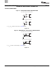
FILTERING
ONE-SHOT COMMAND
Remote junction temperature sensors are usually
For the TMP512/13, when the temperature core is in
implemented in a noisy environment. Noise is
shutdown and the voltage core is in triggered mode, a
frequently generated by fast digital signals and if not
single conversion is started on all enabled channels
filtered properly will induce errors that can corrupt
by writing a '1' to the OS bit in Configuration Register
temperature measurements. The TMP512/13 have a
1. This write operation starts one conversion; the
built-in 65kHz filter on the inputs of DXP and DXN to
TMP512/13 returns to shutdown mode when that
minimize the effects of noise. However, a bypass
conversion completes. At the end of the conversion,
capacitor placed differentially across the inputs of the
the Conversion Ready flags (bit 6 and bit 5) in the
remote temperature sensor is recommended to make
Status Register are set to indicate end of conversion.
the application more robust against unwanted
coupled signals. The value of this capacitor should be
20 Copyright © 2010–2011, Texas Instruments Incorporated