
Datasheet


TMP512
TMP513
www.ti.com
SBOS491A –JUNE 2010– REVISED MAY 2011
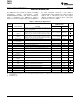
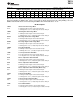
Table 3. Summary of Register Set (continued)
POINTER
ADDRESS POWER-ON RESET
HEX REGISTER NAME FUNCTION BINARY HEX TYPE
(1)
Remote Temperature
12 Contains positive limit for remote temperature. 00101010 10000000 2A80 R/W
Limit 1
Remote Temperature
13 Contains positive limit for remote temperature. 00101010 10000000 2A80 R/W
Limit 2
Remote Temperature
14
(4)
Contains positive limit for remote temperature. 00101010 10000000 2A80 R/W
Limit 3
Sets the current that corresponds to a full-scale drop across the
15 Shunt Calibration Register 00000000 00000000 0000 R/W
shunt.
Contains the N-factor value for Remote Channel 1 and
16 n-Factor 1 00000000 00000000 0000 R/W
Hysteresis for temperature limits.
17 n-Factor 2 Contains the N-factor value for Remote Channel 2. 00000000 00000000 0000 R/W
18
(4)
n-Factor 3 Contains the N-factor value for Remote Channel 3. 00000000 00000000 0000 R/W
1E/FE Manufacturer ID Register Contains the Manufacturer ID. 01010101 11111111 55FF R
TMP512 Device ID
1F/FF Contains the Device ID. 00100010 11111111 22FF R
Register
TMP513 Device ID
1F/FF Contains the Device ID. 00100011 11111111 23FF R
Register
(4) For TMP513 only.
space
space
REGISTER DETAILS
All TMP512/13 registers are 16-bit registers. 16-bit register data are sent in two 8-bit bytes via the two-wire
interface.
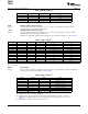
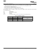
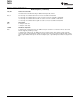
Configuration Register 1—Shunt Measurement Configuration 00h (Read/Write)
BIT # D15 D14 D13 D12 D11 D10 D9 D8 D7 D6 D5 D4 D3 D2 D1 D0
BIT ONE-
RST BRNG PG1 PG0 BADC4 BADC3 BADC2 BADC1 SADC4 SADC3 SADC2 SADC1 MODE3 MODE2 MODE1
NAME SHOT
POR
0 0 1 1 1 0 0 1 1 0 0 1 1 1 1 1
VALUE
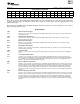
Bit Descriptions
RST: Reset Bit
Bit 15 Setting this bit to '1' generates a system reset that is the same as power-on reset. Resets all registers to default
values; this bit self-clears.
ONE-SHOT One-Shot Bit
Bit 14 Setting this bit to '1' generates a one-shot command.
BRNG: Bus Voltage Range
Bit 13 0 = 16V FSR
1 = 32V FSR (default value)
PG: PGA (Shunt Voltage Only)
Bits 12, 11 Sets PGA gain and range. Note that the PGA defaults to ÷8 (320mV range). Table 4 shows the gain and range for
the various product gain settings.
Copyright © 2010–2011, Texas Instruments Incorporated 33