
Datasheet


TMP512
TMP513
www.ti.com
SBOS491A –JUNE 2010– REVISED MAY 2011
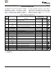
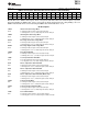
Status Register 02h (Read)
BIT # D15 D14 D13 D12 D11 D10 D9 D8 D7 D6 D5 D4 D3 D2 D1 D0
BIT
SHP SHN BVP BVN PWR LCL RM1 RM2 RM3 CVR CRT PVLD SMBA OVF — —
NAME
POR
0 0 0 0 0 0 0 0 0 0 0 0 0 0 0 0
VALUE
The Status Register flags activate whenever any limit is violated, and latch if the alert is in latch mode. In latch
mode, these flags are cleared when the Status Register is read (if the limit is exceeded, then at next conversion
end, the flag sets again). In transparent mode, these flags are cleared when any corresponding limit is not
violated any longer.
After power-up and initial setup, the Status Register should be read once to clear any flags set as a result of
power-up values prior to setup.
Bit Descriptions
SHP: Shunt Positive Over-Voltage
Bit 15 This bit is set to '1' when the result in the Shunt Voltage Register (04h) exceeds the level set in the Shunt Positive
Limit Register (0Ch).
SHN: Shunt Negative Under-Voltage
Bit 14 This bit is set to '1' when the result in the Shunt Voltage Register (04h) goes below the level set in the Shunt
Negative Limit Register (0Dh).
BVP: Bus Positive Over-Voltage
Bit 13 This bit is set to '1' when the result in the Bus Voltage Register (05h) exceeds the level set in the Bus Voltage
Positive Limit Register (0Eh).
BVN: Bus Negative Under-Voltage
Bit 12 This bit is set to '1' when the result in the Bus Voltage Register (05h) goes below the level set in the Bus Voltage
Negative Limit Register (0Fh).
PWR: Power Over–Limit
Bit 11 This bit is set to '1' when the result in the Power Register (06h) exceeds the level set in the Power Limit Register
(10h).
LCL: Local Temperature Over-Limit
Bit 10 This bit is set to '1' when the result in the Local Temperature Result Register (08h) exceeds the level set in the
Local Temperature Limit Register (11h) plus half of the temperature hysteresis. It clears in transparent mode when
the result in the Local Temperature Result Register (08h) is below the level set in the Local Temperature Limit
Register (11h) minus half of the temperature hysteresis.
RM1: Remote Temperature 1 Over-Limit
Bit 9 This bit is set to '1' when the result in the Remote Temperature Result 1 Register (09h) exceeds the level set in the
Remote Temperature Limit 1 Register (12h) plus half of the temperature hysteresis. It also sets if, during conversion
of remote channel 1, an open diode condition was detected. It clears in transparent mode when the result in the
Remote Temperature Result 1 Register (09h) is below the level set in the Remote Temperature Limit 1 Register
(12h) minus half of the temperature hysteresis, and the last conversion of channel 1 was done without open-diode
detection.
RM2: Remote Temperature 2 Over-Limit
Bit 8 This bit is set to '1' when the result in the Remote Temperature Result 2 Register (0Ah) exceeds the level set in the
Remote Temperature Limit 2 Register (13h) plus half of the temperature hysteresis. It also sets if, during conversion
of remote channel 2, an open diode condition was detected. It clears in transparent mode when the result in the
Remote Temperature Result 2 Register (0Ah) is below the level set in the Remote Temperature Limit 2 Register
(13h) minus half of the temperature hysteresis, and the last conversion of channel 2 was done without open-diode
detection.
Copyright © 2010–2011, Texas Instruments Incorporated 37