
Calculator User Manual

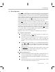
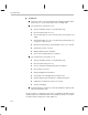
Table Of Contents
- Read This First
- Contents
- Figures
- Tables
- Examples
- Cautions
- Introduction
- Architectural Overview
- Central Processing Unit
- Memory and I/O Spaces
- Program Control
- Addressing Modes
- Assembly Language Instructions
- Instruction Set Summary
- How To Use the Instruction Descriptions
- Instruction Descriptions
- ABS
- ABS
- ADD
- ADD
- ADD
- ADD
- ADDC
- ADDC
- ADDS
- ADDS
- ADDT
- ADDT
- ADRK
- AND
- AND
- AND
- APAC
- APAC
- B
- BACC
- BANZ
- BANZ
- BCND
- BCND
- BIT
- BIT
- BITT
- BITT
- BLDD
- BLDD
- BLDD
- BLDD
- BLDD
- BLPD
- BLPD
- BLPD
- BLPD
- CALA
- CALL
- CC
- CC
- CLRC
- CLRC
- CMPL
- CMPR
- DMOV
- DMOV
- IDLE
- IN
- IN
- INTR
- LACC
- LACC
- LACC
- LACL
- LACL
- LACL
- LACT
- LACT
- LAR
- LAR
- LAR
- LDP
- LDP
- LPH
- LPH
- LST
- LST
- LST
- LST
- LT
- LT
- LTA
- LTA
- LTD
- LTD
- LTD
- LTP
- LTP
- LTS
- LTS
- MAC
- MAC
- MAC
- MAC
- MACD
- MACD
- MACD
- MACD
- MACD
- MAR
- MAR
- MPY
- MPY
- MPY
- MPYA
- MPYA
- MPYS
- MPYS
- MPYU
- MPYU
- NEG
- NEG
- NMI
- NOP
- NORM
- NORM
- NORM
- OR
- OR
- OR
- OUT
- OUT
- PAC
- POP
- POP
- POPD
- POPD
- PSHD
- PSHD
- PUSH
- RET
- RETC
- ROL
- ROR
- RPT
- RPT
- SACH
- SACH
- SACL
- SACL
- SAR
- SAR
- SBRK
- SETC
- SETC
- SFL
- SFR
- SFR
- SPAC
- SPH
- SPH
- SPL
- SPL
- SPLK
- SPLK
- SPM
- SQRA
- SQRA
- SQRS
- SQRS
- SST
- SST
- SUB
- SUB
- SUB
- SUB
- SUBB
- SUBB
- SUBC
- SUBC
- SUBS
- SUBS
- SUBT
- SUBT
- TBLR
- TBLR
- TBLR
- TBLW
- TBLW
- TBLW
- TRAP
- XOR
- XOR
- XOR
- ZALR
- ZALR
- On-Chip Peripherals
- Synchronous Serial Port
- Asynchronous Serial Port
- TMS320C209
- Register Summary
- TMS320C1x/C2x/C2xx/C5x Instruction Set Comparison
- Program Examples
- Submitting ROM Codes to TI
- Design Considerations for Using XDS510 Emulator
- E.1 Designing Your Target System’s Emulator Connector (14-Pin Header)
- E.2 Bus Protocol
- E.3 Emulator Cable Pod
- E.4 Emulator Cable Pod Signal Timing
- E.5 Emulation Timing Calculations
- E.6 Connections Between the Emulator and the Target System
- E.7 Physical Dimensions for the 14-Pin Emulator Connector
- E.8 Emulation Design Considerations
- Glossary
- Index

Power-Down Mode
5-36
5.8 Power-Down Mode
The ’C2xx has a power-down mode that allows the ’C2xx core to enter a dor-
mant state and use less power than during normal operation. Executing an
IDLE instruction initiates power-down mode. When the IDLE instruction
executes, the program counter is incremented once, and then all CPU activi-
ties are halted. While the ’C2xx is in power-down mode, all of its internal con-
tents are maintained. The content of all on-chip RAM remains unchanged. The
peripheral circuits continue to operate, allowing the serial ports and the timer
to take the CPU out of the power-down state. The CLKOUT1 pin remains ac-
tive if bit 0 of the CLK register is set to 0.
The methods for terminating power-down mode depend on whether the pow-
er-down was initiated under normal circumstances or as part of a HOLD opera-
tion. The following subsections describe the differences.
5.8.1 Normal Termination of Power-Down Mode
If power-down has been initiated, any hardware interrupt (internal or external)
takes the processor out of the IDLE state. If you use reset or NMI
, the CPU will
immediately execute the corresponding interrupt service routine. In addition,
if you use reset, registers will assume their reset values.
For a maskable hardware interrupt to wake the processor, it must be un-
masked by the interrupt mask register (IMR bit = 1). However, if the interrupt
is unmasked and is then requested, the processor will leave the IDLE state re-
gardless of the value of the INTM bit (bit 9 of status register ST0). The value
of the INTM bit will only determine the action of the CPU
after
power-down has
been terminated:
INTM = 0. The interrupt is enabled, and the CPU executes the correspond-
ing interrupt service routine.
INTM = 1. The interrupt is disabled, and the CPU continues with the
instruction after IDLE.
If you do not want the CPU to follow an interrupt service routine before continu-
ing with the interrupted program sequence:
Do not use reset or NMI to bring the processor out of power-down.
Make sure your program globally disables maskable interrupts (sets INTM
to 1) before IDLE is executed.