
Calculator User Manual

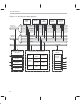
Table Of Contents
- Read This First
- Contents
- Figures
- Tables
- Examples
- Cautions
- Introduction
- Architectural Overview
- Central Processing Unit
- Memory and I/O Spaces
- Program Control
- Addressing Modes
- Assembly Language Instructions
- Instruction Set Summary
- How To Use the Instruction Descriptions
- Instruction Descriptions
- ABS
- ABS
- ADD
- ADD
- ADD
- ADD
- ADDC
- ADDC
- ADDS
- ADDS
- ADDT
- ADDT
- ADRK
- AND
- AND
- AND
- APAC
- APAC
- B
- BACC
- BANZ
- BANZ
- BCND
- BCND
- BIT
- BIT
- BITT
- BITT
- BLDD
- BLDD
- BLDD
- BLDD
- BLDD
- BLPD
- BLPD
- BLPD
- BLPD
- CALA
- CALL
- CC
- CC
- CLRC
- CLRC
- CMPL
- CMPR
- DMOV
- DMOV
- IDLE
- IN
- IN
- INTR
- LACC
- LACC
- LACC
- LACL
- LACL
- LACL
- LACT
- LACT
- LAR
- LAR
- LAR
- LDP
- LDP
- LPH
- LPH
- LST
- LST
- LST
- LST
- LT
- LT
- LTA
- LTA
- LTD
- LTD
- LTD
- LTP
- LTP
- LTS
- LTS
- MAC
- MAC
- MAC
- MAC
- MACD
- MACD
- MACD
- MACD
- MACD
- MAR
- MAR
- MPY
- MPY
- MPY
- MPYA
- MPYA
- MPYS
- MPYS
- MPYU
- MPYU
- NEG
- NEG
- NMI
- NOP
- NORM
- NORM
- NORM
- OR
- OR
- OR
- OUT
- OUT
- PAC
- POP
- POP
- POPD
- POPD
- PSHD
- PSHD
- PUSH
- RET
- RETC
- ROL
- ROR
- RPT
- RPT
- SACH
- SACH
- SACL
- SACL
- SAR
- SAR
- SBRK
- SETC
- SETC
- SFL
- SFR
- SFR
- SPAC
- SPH
- SPH
- SPL
- SPL
- SPLK
- SPLK
- SPM
- SQRA
- SQRA
- SQRS
- SQRS
- SST
- SST
- SUB
- SUB
- SUB
- SUB
- SUBB
- SUBB
- SUBC
- SUBC
- SUBS
- SUBS
- SUBT
- SUBT
- TBLR
- TBLR
- TBLR
- TBLW
- TBLW
- TBLW
- TRAP
- XOR
- XOR
- XOR
- ZALR
- ZALR
- On-Chip Peripherals
- Synchronous Serial Port
- Asynchronous Serial Port
- TMS320C209
- Register Summary
- TMS320C1x/C2x/C2xx/C5x Instruction Set Comparison
- Program Examples
- Submitting ROM Codes to TI
- Design Considerations for Using XDS510 Emulator
- E.1 Designing Your Target System’s Emulator Connector (14-Pin Header)
- E.2 Bus Protocol
- E.3 Emulator Cable Pod
- E.4 Emulator Cable Pod Signal Timing
- E.5 Emulation Timing Calculations
- E.6 Connections Between the Emulator and the Target System
- E.7 Physical Dimensions for the 14-Pin Emulator Connector
- E.8 Emulation Design Considerations
- Glossary
- Index

Memory and I/O Spaces
2-8
CPU reads data on the third cycle and writes data on the fourth cycle. However,
DARAM allows the CPU to write and read in one cycle; the CPU writes to
DARAM on the master phase of the cycle and reads from DARAM on the slave
phase. For example, suppose two instructions, A and B, store the accumulator
value to DARAM and load the accumulator with a new value from DARAM.
Instruction A stores the accumulator value during the master phase of the CPU
cycle, and instruction B loads the new value to the accumulator during the
slave phase. Because part of the dual-access operation is a write, it only ap-
plies to RAM.
2.3.2 Single-Access On-Chip Program/Data RAM
Some of the ’C2xx devices have 4K 16-bit words of single-access RAM
(SARAM). The addresses associated with the SARAM can be used for both
data memory and program memory and are software- or hardware-configur-
able (depending on the device) to either external memory or the internal
SARAM. When configured as external, these addresses can be used for off-
chip data and program memory. Code can be booted from off-chip ROM and
then executed at full speed once it is loaded into the on-chip SARAM. Because
the SARAM can be mapped to program and/or data memory, the SARAM al-
lows for more flexible address mapping than the DARAM block.
SARAM is accessed only once per CPU cycle. When the CPU requests multi-
ple accesses, the SARAM schedules the accesses by providing a not-ready
condition to the CPU and then executing the accesses one per cycle. For ex-
ample, if the instruction sequence involves storing the accumulator value and
then loading a value to the accumulator, it would take two cycles to complete
in SARAM, compared to one cycle in DARAM.
2.3.3 Factory-Masked On-Chip ROM
Some of the ’C2xx devices feature an on-chip, 4K 16-bit words of program-
mable ROM. The ROM can be selected during reset by driving the MP/MC
pin
low. If the ROM is not selected, the device starts its execution from off-chip
memory.
If you want a custom ROM, you can provide the code or data to be pro-
grammed into the ROM in object file format, and Texas Instruments will gener-
ate the appropriate process mask to program the ROM. See Appendix D for
details on how to submit ROM code to Texas Instruments.