
Calculator User Manual
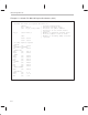
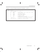
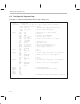
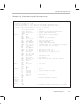
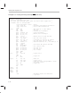
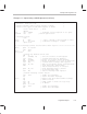
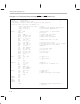
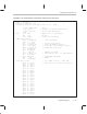
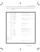
Table Of Contents
- Read This First
- Contents
- Figures
- Tables
- Examples
- Cautions
- Introduction
- Architectural Overview
- Central Processing Unit
- Memory and I/O Spaces
- Program Control
- Addressing Modes
- Assembly Language Instructions
- Instruction Set Summary
- How To Use the Instruction Descriptions
- Instruction Descriptions
- ABS
- ABS
- ADD
- ADD
- ADD
- ADD
- ADDC
- ADDC
- ADDS
- ADDS
- ADDT
- ADDT
- ADRK
- AND
- AND
- AND
- APAC
- APAC
- B
- BACC
- BANZ
- BANZ
- BCND
- BCND
- BIT
- BIT
- BITT
- BITT
- BLDD
- BLDD
- BLDD
- BLDD
- BLDD
- BLPD
- BLPD
- BLPD
- BLPD
- CALA
- CALL
- CC
- CC
- CLRC
- CLRC
- CMPL
- CMPR
- DMOV
- DMOV
- IDLE
- IN
- IN
- INTR
- LACC
- LACC
- LACC
- LACL
- LACL
- LACL
- LACT
- LACT
- LAR
- LAR
- LAR
- LDP
- LDP
- LPH
- LPH
- LST
- LST
- LST
- LST
- LT
- LT
- LTA
- LTA
- LTD
- LTD
- LTD
- LTP
- LTP
- LTS
- LTS
- MAC
- MAC
- MAC
- MAC
- MACD
- MACD
- MACD
- MACD
- MACD
- MAR
- MAR
- MPY
- MPY
- MPY
- MPYA
- MPYA
- MPYS
- MPYS
- MPYU
- MPYU
- NEG
- NEG
- NMI
- NOP
- NORM
- NORM
- NORM
- OR
- OR
- OR
- OUT
- OUT
- PAC
- POP
- POP
- POPD
- POPD
- PSHD
- PSHD
- PUSH
- RET
- RETC
- ROL
- ROR
- RPT
- RPT
- SACH
- SACH
- SACL
- SACL
- SAR
- SAR
- SBRK
- SETC
- SETC
- SFL
- SFR
- SFR
- SPAC
- SPH
- SPH
- SPL
- SPL
- SPLK
- SPLK
- SPM
- SQRA
- SQRA
- SQRS
- SQRS
- SST
- SST
- SUB
- SUB
- SUB
- SUB
- SUBB
- SUBB
- SUBC
- SUBC
- SUBS
- SUBS
- SUBT
- SUBT
- TBLR
- TBLR
- TBLR
- TBLW
- TBLW
- TBLW
- TRAP
- XOR
- XOR
- XOR
- ZALR
- ZALR
- On-Chip Peripherals
- Synchronous Serial Port
- Asynchronous Serial Port
- TMS320C209
- Register Summary
- TMS320C1x/C2x/C2xx/C5x Instruction Set Comparison
- Program Examples
- Submitting ROM Codes to TI
- Design Considerations for Using XDS510 Emulator
- E.1 Designing Your Target System’s Emulator Connector (14-Pin Header)
- E.2 Bus Protocol
- E.3 Emulator Cable Pod
- E.4 Emulator Cable Pod Signal Timing
- E.5 Emulation Timing Calculations
- E.6 Connections Between the Emulator and the Target System
- E.7 Physical Dimensions for the 14-Pin Emulator Connector
- E.8 Emulation Design Considerations
- Glossary
- Index

Task-Specific Program Code
C-9
Program Examples
Example C–5. Testing and Using the Timer (timer.asm)
* File: timer.asm *
* Function: Timer test code *
* PRD=0x00ff,TDDR=f @ 50ns, gives an interrupt interval=205us *
* PRD=0xffff,TDDR=0 @ 50ns, gives an interrupt interval=3.27ms*
* Timer interval measurable on I/O 2,3 or xf pins *
.title ”Timer Test” ; Title
.copy ”init.h” ; Variable and register declaration
.copy ”vector.h” ; Vector label declaration
.text
start: clrc CNF ; Map block B0 to data memory
ldp #0h ; set DP=0
setc INTM ; Disable all interrupts
splk #0000h,60h
out 60h, wsgr ; Set zero wait states
splk #0ffffh,ifr ; clear interrupts
splk #0004h,imr ; enable timer interrupt
splk #0e00ch, 60h ; configure bit I/O I03 and IO2 as outputs
out 60h, aspcr ; set the aspcr for the above
mar *,ar1
lar ar1,#rxbuf
splk #0004h,61h ; bit value to set I/O 2
splk #0008h,62h ; bit value to set I/O 3
out 61h,iosr ; set the bit 2 = high, 3= zero
splk #0000h, 63h
splk #00ffh, 64h
out 64h, prd ; set PRD=0x00ffh
out 63h, tim ; set TIM=0x0000
splk #0c2fh, 64h ; PSC, TDDR are zero, reload, restart
out 64h, tcr
clrc intm
clrc xf
wait: out 62h,iosr ; set io2=0
idle
clrc xf
b wait
timer: setc xf ; xf =1
in 68h,tcr ; Read tcr,prd, tim regs.
in 69h,prd
in 6ah,tim
out 61h,iosr ; set io2=1
clrc intm
ret
inpt1: ret ; Unused interrupt routines
inpt23: ret
codtx: ret
codrx: ret
uart: ret
.end ; Assembler module end directive –optional