
Digital Signal Processor Product Preview

www.ti.com
PRODUCT PREVIEW
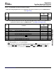
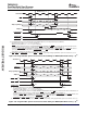
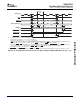
AECLKOUT
ACEx
ABE[7:0]
AEA[19:0]/
ABA[1:0]
AED[63:0]
AAOE/ASOE
(A)
AR/W
AAWE/ASWE
(A)
AARDY
(B)
Byte Enables
Address
Read Data
Hold = 1
2
Strobe = 4
Setup = 1
2
2
4
10
10
1
1
1
3
A AAOE/ASOE and AAWE/ASWE operate as AAOE (identified under select signals) and AAWE, respectively, during asynchronous
memory accesses.
B Polarity of the AARDY signal is programmable through the AP field of the EMIFA Async Wait Cycle Configuration register (AWCC).
DEASSERTED
TMS320C6454
Fixed-Point Digital Signal Processor
SPRS311A – APRIL 2006 – REVISED DECEMBER 2006
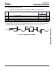
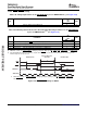
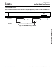
Table 7-45. Switching Characteristics Over Recommended Operating Conditions for Asynchronous
Memory Cycles for EMIFA Module
(1) (2) (3)
(see Figure 7-33 and Figure 7-34 )
-720
-850
NO. PARAMETER UNIT
-1000
MIN MAX
1 t
osu(SELV-AOEL)
Output setup time, select signals valid to AAOE low RS * E – 1.5 ns
2 t
oh(AOEH-SELIV)
Output hold time, AAOE high to select signals invalid RS * E – 1.9 ns
10 t
d(EKOH-AOEV)
Delay time, AECLKOUT high to AAOE valid 1 7 ns
11 t
osu(SELV-AWEL)
Output setup time, select signals valid to AAWE low WS * E – 1.7 ns
12 t
oh(AWEH-SELIV)
Output hold time, AAWE high to select signals invalid WH * E – 1.8 ns
13 t
d(EKOH-AWEV)
Delay time, AECLKOUT high to AAWE valid 1.3 7.1 ns
(1) E = AECLKOUT period in ns for EMIFA
(2) RS = Read setup, RST = Read strobe, RH = Read hold, WS = Write setup, WST = Write strobe, WH = Write hold. These parameters
are programmed via the EMIFA CE Configuration registers (CEnCFG).
(3) Select signals for EMIFA include: ACEx, ABE[7:0], AEA[19:0], ABA[1:0]; and for EMIFA writes, also include AR/ W, AED[63:0].
Figure 7-33. Asynchronous Memory Read Timing for EMIFA
Submit Documentation Feedback C64x+ Peripheral Information and Electrical Specifications 153