
Digital Signal Processor Product Preview

www.ti.com
PRODUCT PREVIEW
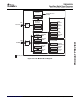
7.12.3 HPI Electrical Data/Timing
TMS320C6454
Fixed-Point Digital Signal Processor
SPRS311A – APRIL 2006 – REVISED DECEMBER 2006
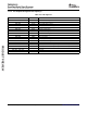
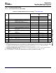
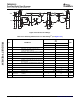
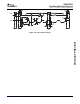
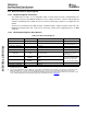
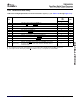
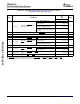
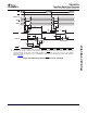
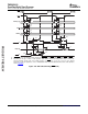
Table 7-55. Timing Requirements for Host-Port Interface Cycles
(1) (2)
(see Table 7-56 through Figure 7-51 )
-720
-850
NO. UNIT
-1000
MIN MAX
9 t
su(HASL-HSTBL)
Setup time, HAS low before HSTROBE low 5 ns
10 t
h(HSTBL-HASL)
Hold time, HAS low after HSTROBE low 2 ns
11 t
su(SELV-HASL)
Setup time, select signals
(3)
valid before HAS low 5 ns
12 t
h(HASL-SELV)
Hold time, select signals
(3)
valid after HAS low 5 ns
13 t
w(HSTBL)
Pulse duration, HSTROBE low 15 ns
14 t
w(HSTBH)
Pulse duration, HSTROBE high between consecutive accesses 2M ns
15 t
su(SELV-HSTBL)
Setup time, select signals
(3)
valid before HSTROBE low 5 ns
16 t
h(HSTBL-SELV)
Hold time, select signals
(3)
valid after HSTROBE low 5 ns
17 t
su(HDV-HSTBH)
Setup time, host data valid before HSTROBE high 5 ns
18 t
h(HSTBH-HDV)
Hold time, host data valid after HSTROBE high 1 ns
37 t
su(HCSL-HSTBL)
Setup time, HCS low before HSTROBE low 0 ns
Hold time, HSTROBE low after HRDY low. HSTROBE should not be
38 t
h(HRDYL-HSTBL)
inactivated until HRDY is active (low); otherwise, HPI writes will not 1.1 ns
complete properly.
(1) HSTROBE refers to the following logical operation on HCS, HDS1, and HDS2: [NOT( HDS1 XOR HDS2)] OR HCS.
(2) M = SYSCLK3 period = 6/CPU clock frequency in ns. For example, when running parts at 1000 MHz, use M = 6 ns.
(3) Select signals include: HCNTL[1:0] and HR/ W. For HPI16 mode only, select signals also include HHWIL.
Submit Documentation Feedback C64x+ Peripheral Information and Electrical Specifications 167