
Digital Signal Processor Product Preview

www.ti.com
PRODUCT PREVIEW
7.16 Peripheral Component Interconnect (PCI)
7.16.1 PCI Device-Specific Information
TMS320C6454
Fixed-Point Digital Signal Processor
SPRS311A – APRIL 2006 – REVISED DECEMBER 2006
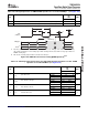
The C6454 DSP supports connections to a PCI backplane via the integrated PCI master/slave bus
interface. The PCI port interfaces to DSP internal resources via the data switched central resource. The
data switched central resource is described in more detail in Section 4 .
For more detailed information on the PCI port peripheral module, see the TMS320C645x DSP Peripheral
Component Interconnect (PCI) User's Guide (literature number SPRUE60 ).
The PCI peripheral on the C6454 DSP conforms to the PCI Local Bus Specification (version 2.3). The PCI
peripheral can act both as a PCI bus master and as a target. It supports PCI bus operation of speeds up
to 66 MHz and uses a 32-bit data/address bus.
On the C6454 device, the pins of the PCI peripheral are multiplexed with the pins of the HPI and GPIO
peripherals. PCI functionality for these pins is controlled (enabled/disabled) by the PCI_EN pin (Y29). The
maximum speed of the PCI, 33 MHz or 66 MHz, is controlled through the PCI66 pin (U27). For more
detailed information on the peripheral control, see Section 3 , Device Configuration.
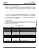
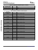
The C6454 device provides an initialization mechanism through which the default values for some of the
PCI configuration registers can be read from an I2C EEPROM. Table 7-96 shows the registers which can
be initialized through the PCI auto-initialization. Also shown is the default value of these registers when
PCI auto-initialization is not used. PCI auto-initialization is controlled (enabled/disabled) through the
PCI_EEAI pin (P25). For more information on this feature, see the TMS320C645x DSP Peripheral
Component Interconnect (PCI) User's Guide (literature number SPRUE60 ) and the TMS320C645x
Bootloader User's Guide (literature number SPRUEC6 ).
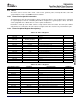
Table 7-96. Default Values for PCI Configuration
Registers
DEFAULT
REGISTER
VALUE
Vendor ID/Device ID Register (PCIVENDEV) 104C B000h
Class Code/Revision ID Register (PCICLREV) 0000 0001h
Subsystem Vendor ID/Subsystem ID Register 0000 0000h
(PCISUBID)
Max Latency/Min Grant/Interrupt Pin/Interrupt Line 0000 0100h
Register (PCILGINT)
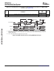
The on-chip Bootloader supports a host boot which allows an external PCI device to load application code
into the DSP's memory space. The PCI boot is terminated when the Host generates a DSP interrupt. The
Host can generate a DSP interrupt through the PCI peripheral by setting the DSPINT bit in the Back-End
Application Interrupt Enable Set Register (PCIBINTSET) and the Status Set Register (PCISTATSET). For
more information on the boot sequence of the C6454 DSP, see Section 2.4 .
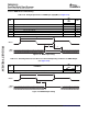
NOTE
After the host boot is complete, the DSP interrupt is registered in bit 0 (channel 0) of the
EDMA Event Register (ER). This event must be cleared by software before triggering
transfers on DMA channel 0.
Submit Documentation Feedback C64x+ Peripheral Information and Electrical Specifications 207