
Digital Signal Processor Product Preview

www.ti.com
PRODUCT PREVIEW
TMS320C6454
Fixed-Point Digital Signal Processor
SPRS311A – APRIL 2006 – REVISED DECEMBER 2006
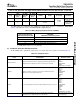
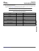
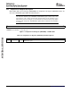
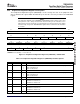
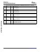
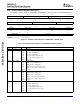
Table 3-1. C6454 Device Configuration Pins (AEA[19:0], ABA[1:0], and PCI_EN) (continued)
CONFIGURATION IPD/
NO. FUNCTIONAL DESCRIPTION
PIN IPU
(1)
HPI peripheral bus width select (HPI_WIDTH).
0 HPI operates in HPI16 mode (default).
HPI bus is 16 bits wide; HD[15:0] pins are used and the remaining HD[31:16]
pins are reserved pins in the Hi-Z state.
AEA14 R25 IPD
1 HPI operates in HPI32 mode.
HPI bus is 32 bits wide; HD[31:0] pins are used.
Applies only when HPI function of HPI/PCI multiplexed pins is selected (PCI_EN pin = 0).
Device Endian mode (LENDIAN).
AEA13 R27 IPU 0 System operates in Big Endian mode.
1 System operates in Little Endian mode (default).
For proper C6454 device operation, this pin must be externally pulled down with a 1-k Ω
AEA12 R28 IPD
resistor at device reset.
For proper C6454 device operation, this pin must be externally pulled down with a 1-k Ω
AEA11 T25 IPD
resistor at device reset.
EMAC Interface Selects (MACSEL[1:0]).
These pins select the interface used by the EMAC/MDIO peripheral.
00 10/100 EMAC/MDIO with MII Interface [default]
[M25,
01 10/100 EMAC/MDIO with RMII Interface
AEA[10:9] IPD
M27]
10 10/100/1000 EMAC/MDIO with GMII Interface
11 10/100/1000 EMAC/MDIO with RGMII Interface
For more detailed information on the MAC_SEL[1:0] control pin selections, see Table 3-3 .
PCI I2C EEPROM Auto-Initialization (PCI_EEAI).
PCI auto-initialization via external I2C EEPROM
0 PCI auto-initialization through external I2C EEPROM is disabled. The PCI
peripheral uses the specified PCI default values (default).
AEA8 P25 IPD
1 PCI auto-initialization through external I2C EEPROM is enabled. The PCI
peripheral is configured through external I2C EEPROM provided the PCI
peripheral pins are enabled (PCI_EN = 1).
Note: If the PCI pin function is disabled (PCI_EN pin = 0), this pin must not be pulled up.
AEA7 N27 IPD For proper C6454 device operation, do not oppose the IPD on this pin.
PCI Frequency Selection (PCI66).
Selects the operating frequency of the PCI (either 33 MHz or 66 MHz).
0 PCI operates at 33 MHz (default)
AEA6 U27 IPD
1 PCI operates at 66 MHz
Note: If the PCI pin function is disabled (PCI_EN pin = 0), this pin must not be pulled up.
McBSP1 pin function enable bit (MCBSP1_EN).
Selects which function is enabled on the McBSP1/GPIO multiplexed pins.
0 GPIO pin function enabled (default).
AEA5 U28 IPD
This means all multiplexed McBSP1/GPIO pins function as GPIO pins.
1 McBSP1 pin function enabled.
This means all multiplexed McBSP1/GPIO pins function as McBSP1 pins.
SYSCLKOUT Enable bit (SYSCLKOUT_EN).
Selects which function is enabled on the SYSCLK4/GP[1] muxed pin.
AEA4 T28 IPD
0 GP[1] pin function is enabled (default)
1 SYSCLK4 pin function is enabled
For proper C6454 device operation, the AEA3 pin must be pulled down to V
SS
using a 1-k Ω
AEA3 T27 IPD
resistor.
Configuration General-Purpose Inputs (CFGGP[2:0])
[T26,
The value of these pins is latched to the Device Status Register following device reset and is
AEA[2:0] U26, IPD
used by the on-chip bootloader for some boot modes. For more information on the boot
U25]
modes, see Section 2.4 , Boot Sequence.
Submit Documentation Feedback Device Configuration 51