
Computer Hardware User Manual


DDR2 Memory Controller Registers
www.ti.com
4.2 DDR2 Memory Controller Status Register (DMCSTAT)
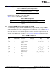
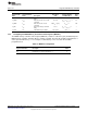
The DDR2 memory controller status register (DMCSTAT) is shown in Figure 20
Figure 20. DDR2 Memory Controller Status Register (DMCSTAT)
31 30 29 16
BE Rsvd Reserved
R-0x0 R-0x1 R-0x0
15 3 2 1 0
Reserved IFRDY Reserved
R-0x0 R-0x0 R-0x0
LEGEND: R/W = Read/Write; R = Read only; -n = value after reset
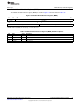
Table 19. DDR2 Memory Controller Status Register (DMCSTAT) Field Descriptions
Bit Field Value Description
31 BE Big endian bit. Reflects whether the DDR2 Memory Controller is configured for big- or
little-endian mode.
0 DDR2 Memory Controller is configured for little-endian mode.
1 DDR2 Memory Controller is configured for big-endian mode.
30 Reserved Reserved. The reserved bit location is always read as 1. A value written to this field has no
effect.
29-3 Reserved 0 Reserved. The reserved bit location is always read as 0. A value written to this field has no
effect.
2 IFRDY DDR2 memory controller interface logic ready bit. The interface logic controls the signals used
to communicate with DDR2 SDRAM devices. This bit displays the status of the interface logic.
0 Interface logic is not ready; either powered down, not ready, or not locked.
1 Interface logic is powered up, locked, and ready for operation.
1-0 Reserved 0 Reserved. The reserved bit location is always read as 0. A value written to this field has no
effect.
40
C6455/C6454 DDR2 Memory Controller SPRU970G– December 2005– Revised June 2011
Submit Documentation Feedback
Copyright © 2005–2011, Texas Instruments Incorporated