TMS320C6457 DSP Host Port Interface (HPI) User's Guide Literature Number: SPRUGK7A March 2009 – Revised July 2010
SPRUGK7A – March 2009 – Revised July 2010 Copyright © 2009–2010, Texas Instruments Incorporated
Preface ....................................................................................................................................... 6 1 Introduction to the HPI ......................................................................................................... 7 ........................................................................................ 8 ........................................................................................... 9 2 Using the Address Registers ................
www.ti.com List of Figures HPI Position in the Host-DSP System 2 Example of Host-DSP Signal Connections When Using the HAS Signal in the 32-Bit Multiplexed Mode 3 Example of Host-DSP Signal Connections When the HAS Signal is Tied High in the 32-Bit Multiplexed Mode ........................................................................................................................
www.ti.com List of Tables ................................................................................................ 1 Summary of HPI Registers 2 HPI Signals .................................................................................................................. 9 3 Options for Connecting Host and HPI Data Strobe Pins ............................................................. 15 4 Access Types Selectable by the HCNTL Signals .......................................................
Preface SPRUGK7A – March 2009 – Revised July 2010 Read This First About This Manual This guide describes the host port interface (HPI) on the TMS320C6457 digital signal processors (DSPs). The HPI enables an external host processor (host) to directly access the internal or external memory of the DSP using a 16-bit (HPI16) or 32-bit (HPI32) interface. Notational Conventions This document uses the following conventions. • Hexadecimal numbers are shown with the suffix h.
User's Guide SPRUGK7A – March 2009 – Revised July 2010 Host Port Interface (HPI) This guide describes the host port interface (HPI) on the TMS320C6457 digital signal processors (DSPs). The HPI enables an external host processor (host) to directly access DSP resources (including internal and external memory) using a 16-bit (HPI16) or 32-bit (HPI32) interface. 1 Introduction to the HPI The HPI provides a parallel port interface through which an external host processor (host) can access DSP resources.
Introduction to the HPI www.ti.com The HPI uses multiplexed operation, meaning the data bus carries both address and data. When the host drives an address on the bus, the address is stored in the address register (HPIA) in the HPI, so that the bus can then be used for data. The HPI supports two interface modes: HPI16 and HPI32 mode. DSP selects either HPI16 or HPI32 mode via the HPI_WIDTH device configuration pin at reset. • 16-bit multiplexed mode (HPI16).
Introduction to the HPI www.ti.com Table 1.
Introduction to the HPI www.ti.com Table 2. HPI Signals (continued) 10 (1) Signal State Host Connection Description HCNTL[1:0] I Address or control pins The HPI latches the logic levels of these pins on the falling edge of HAS or internal HSTRB (for details about internal HSTRB, see Section 3.3). The four binary states of these pins determine the access type of the current transfer (HPIC, HPID with autoincrementing, HPIA, or HPID without autoincrementing).
Using the Address Registers www.ti.com 2 Using the Address Registers The HPI contains two 32-bit address registers: one for read operations (HPIAR) and one for write operations (HPIAW). These roles are unchanging from the position of the HPI DMA logic. HPI DMA logic collects the address from HPIAR when reading from DSP internal/external memory and collects the address from HPIAW when writing to DSP internal/external memory.
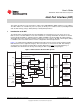
HPI Operation www.ti.com 3 HPI Operation 3.1 Host-HPI Signal Connections Figure 2 and Figure 3 show examples of signal connections for the 32-bit multiplexed mode. Figure 4 and Figure 5 show similar examples for the 16-bit multiplexed mode. In Figure 2 and Figure 4, the HAS signal is used as described in Section 3.6. In Figure 3 and Figure 5, HAS is tied high (not used).
HPI Operation www.ti.com Figure 3. Example of Host-DSP Signal Connections When the HAS Signal is Tied High in the 32-Bit Multiplexed Mode DSP Host HPI Logic high HAS 2 HCNTL[1:0] HHWIL Address or I/O No connect Read/Write HR/W Chip select HCS Logic high Data HDS1 strobeA Data/address HDS2 32 HD[31:0] Ready HRDY HINT Interrupt A Data strobing options are given in Section 3.3. Figure 4.
HPI Operation www.ti.com Figure 5. Example of Host-DSP Signal Connections When the HAS Signal is Tied High in the 16-Bit Multiplexed Mode DSP Host HPI Logic high HAS 2 Address or I/O HCNTL[1:0] Read/Write HR/W Chip select HCS HHWIL Logic high Data HDS2 No connect Data Ready Interrupt A 3.2 HDS1 strobeA 16 16 HD[31:16] HD[15:0] HRDY HINT Data strobing options are given in Section 3.3.
HPI Operation www.ti.com If the host wants to read data from the DSP internal/external memory, the HPI DMA logic reads the memory address from HPIAR and retrieves the data from the addressed memory location. When the data has been placed in HPID, the HPI drives the data onto its HD bus. The HRDY signal informs the host whether the data on the HD bus is valid (HRDY low) or not valid yet (HRDY high).
HPI Operation 3.4 www.ti.com HCNTL[1:0] and HR/W: Indicating the Cycle Type The cycle type consists of: • The access type selected by the host by driving the appropriate levels on the HCNTL[1:0] pins of the HPI. Table 4 describes the four available access types. • The transfer direction that the host selects with the HR/W pin. The host must drive the HR/W signal high (read) or low (write). Table 5 summarizes the cycle types.
HPI Operation www.ti.com 3.5 HHWIL: Identifying the First and Second Halfwords in 16-Bit Multiplexed Mode In the 16-bit multiplexed mode, each host cycle consists of two consecutive halfword transfers. For each transfer, the host must specify the cycle type with HCNTL[1:0] and HR/W, and the host must use HHWIL to indicate whether the first or second halfword is being transferred.
HPI Operation www.ti.com Figure 7. 16-Bit Multiplexed Mode Host Read Cycle Using HAS HCS HAS Internal HSTRB HR/W HCNTL[1:0] HD[15:0] Data 1 Data 2 HRDYA HHWIL HPI latches control information A 18 Host latches HPI latches data control information Host latches data Depending on the type of write operation (HPID without autoincrementing, HPIA, HPIC, or HPID with autoincrementing) and the state of the FIFO, transitions on HRDY may or may not occur. For more information, see Section 3.9.
HPI Operation www.ti.com Figure 8. 16-Bit Multiplexed Mode Host Write Cycle Using HAS HCS HAS HR/W HCNTL[1:0] Internal HSTRB HD[15:0] Data 1 Data 2 HRDYA HHWIL HPI latches control information HPI latches control information HPI latches data A HPI latches data Depending on the type of write operation (HPID without autoincrementing, HPIA, HPIC, or HPID with autoincrementing) and the state of the FIFO, transitions on HRDY may or may not occur. For more information, see Section 3.9.
HPI Operation 3.7 www.ti.com Performing a Multiplexed Access Without HAS The HAS signal is not required when the host processor has dedicated signals (address lines or bit I/O) capable of driving the control lines. Dedicated pins can be directly connected to HCNTL[1:0], HR/W, and HHWIL. Figure 3 and Figure 5 show examples of signal connections when HAS is not used for multiplexed transfers. When HAS is not used, it must be tied high (inactive).
HPI Operation www.ti.com Figure 10. 16-Bit Multiplexed Mode Host Write Cycle With HAS Tied High HCS Internal HSTRB HR/W HCNTL[1:0] HD[15:0] Data 1 Data 2 HRDYA HHWIL HPI latches control information HPI latches control information HPI latches data A HPI latches data Depending on the type of write operation (HPID without autoincrementing, HPIA, HPIC, or HPID with autoincrementing) and the state of the FIFO, transitions on HRDY may or may not occur. For more information, see Section 3.9.
HPI Operation 3.8 www.ti.com Single-Halfword HPIC Cycle in the 16-Bit Multiplexed Mode In 16-bit multiplexed mode, the lower 16 bits of the HPIC registers are duplicated on the upper 16 bits during HPIC host accesses. Therefore, the host only needs to perform a single halfword cycle access to read the HPIC register. The host can drive the HHWIL pin either high or low, and either approach returns the same value.
HPI Operation www.ti.com The following sections describe the behavior of HRDY during HPI register accesses. In all cases, the chip select signal, HCS, must be asserted for HRDY to go high. 3.9.1 HRDY Behavior During 16-Bit Multiplexed Read Operations Figure 12 shows an HPIC (HCNTL[1:0] = 00b) or HPIA (HCNTL[1:0] = 10b) read cycle during 16-bit multiplexed HPI operation. Neither an HPIC read cycle nor an HPIA read cycle causes HRDY to go high. Figure 12.
HPI Operation 3.9.2 www.ti.com HRDY Behavior During 16-Bit Multiplexed Write Operations Figure 15 shows an HPIC (HCNTL[1:0] = 00b) write cycle during 16-bit multiplexed HPI operation. An HPIC write cycle does not cause HRDY to go high. Figure 15. HRDY Behavior During an HPIC Write Cycle in the 16-Bit Multiplexed Mode HCS 00 HCNTL[1:0] 00 HR/W HHWIL Internal HSTRB 1st halfword HD[15:0] 2nd halfword HRDY Figure 16 includes a HPID write cycle without autoincrementing in the 16-bit multiplexed mode.
HPI Operation www.ti.com Figure 18. HRDY Behavior During a Data Write Operation in the 16-Bit Multiplexed Mode (Case 3: Autoincrementing Selected, FIFO Not Empty Before Write) HPIA write HPID+ writes HCS HCNTL[1:0] 10 10 01 01 01 HR/W HHWIL Internal HSTRB 1st halfword 2nd halfword 1st halfword 2nd halfword 1st halfword HD[15:0] HRDY 3.9.
HPI Operation www.ti.com Figure 20. HRDY Behavior During a Data Read Operation in the 16-Bit Multiplexed Mode (Case 1: HPIA Write Cycle Followed by Nonautoincrement HPID Read Cycle) HPIA Write HPID Read HCS HCNTL[1:0] 10 11 HR/W Internal HSTRB HD[31:0] HRDY Figure 21 shows an HPIA (HCNTL[1:0] = 10b) write access followed by several autoincrement HPID (HCNTL[1:0] = 01b) read accesses. Note that HRDY is active for the HPIA access.
HPI Operation www.ti.com Figure 22. HRDY Behavior During an HPIC Write Cycle in the 32-Bit Multiplexed Mode HCS HCNTL[1:0] 00 HR/W Internal HSTRB HD[31:0] HRDY Figure 23 shows an HPIA (HCNTL[1:0] = 10b) write access followed by an HPID (HCNTL[1:0] = 11b) write access for 32-bit multiplexed HPI operation. Figure 23.
HPI Operation www.ti.com Figure 24. HRDY Behavior During a Data Write Operation in the 32-Bit Multiplexed Mode (Case 2: Autoincrementing Selected, FIFO Empty Before Write) HPIA Write HPID+ Writes HCSA HCNTL[1:0] 10 01 01 01 HR/W Internal HSTRB HD[31:0] HRDY A HCS may be brought high during strobe cycles. However, note that HRDY is gated by HCS.
Software Handshaking Using the HPI Ready (HRDY) Bit www.ti.com 4 Software Handshaking Using the HPI Ready (HRDY) Bit In addition to the HRDY output signal, the HPI contains an HRDY bit in the control register (HPIC). This bit is useful for software polling when the host does not have an input pin to connect to the HRDY pin.
Interrupts Between the Host and the CPU 5 www.ti.com Interrupts Between the Host and the CPU The host can interrupt the CPU of the DSP via the DSPINT bit of the HPIC, as described in Section 5.1. The CPU can send an interrupt to the host by using the HINT bit of HPIC, as described in Section 5.2. 5.1 DSPINT Bit: Host-to-CPU Interrupts The DSPINT bit of HPIC allows the host to send an interrupt request to the CPU, as summarized in Figure 26 and detailed following the figure. Figure 26.
Interrupts Between the Host and the CPU www.ti.com Figure 27. CPU-to-Host Interrupt State Diagram No interrupt/ interrupt cleared CPU writes 0 to HINT bit HINT bit=0 Host writes 0 or 1 to HINT bit HINT signal is high CPU writes 1 to HINT bit Interrupt active Host writes 1 to HINT bit HINT bit=1 CPU writes 0 or 1 to HINT bit HINT signal is low Host writes 0 to HINT bit If the CPU writes 1 to the HINT bit of HPIC, the HPI drives the HINT signal low, indicating an interrupt condition to the host.
FIFOs and Bursting 6 www.ti.com FIFOs and Bursting The HPI data register (HPID) is a port through which the host accesses two first-in, first-out buffers (FIFOs). As shown in Figure 28, a read FIFO supports host read cycles, and a write FIFO supports host write cycles. Both read and write FIFOs are 8-words deep (each word is 32 bits). If the host is performing multiple reads or writes to consecutive memory addresses (autoincrement HPID cycles), the FIFOs are used for bursting.
FIFOs and Bursting www.ti.com If the host initiates an HPID read cycle with autoincrementing, the HPI DMA logic performs two 4-word burst operations to fill the read FIFO. The host is initially held off by the deassertion of the HRDY signal until data is available to be read from the read FIFO. Once data is available in the read FIFO, the host can read data from the read FIFO by performing subsequent reads of HPID with autoincrementing.
FIFOs and Bursting 6.3 www.ti.com FIFO Flush Conditions When specific conditions occur within the HPI, the read or write FIFO must be flushed to prevent the reading of stale data from the FIFOs. When a read FIFO flush condition occurs, all current host accesses and direct memory accesses (DMAs) to the read FIFO are allowed to complete. This includes DMAs that have been requested but not yet initiated. The read FIFO pointers are then reset, causing any read data to be discarded.
Emulation and Reset Considerations www.ti.com 7 Emulation and Reset Considerations 7.1 Emulation Modes The FREE and SOFT bits of the power and emulation management register (PWREMU_MGMT) determine the response of the HPI to an emulation suspend condition. If FREE = 1, the HPI is not affected, and the SOFT bit has no effect. If FREE = 0 and SOFT = 0, the HPI is not affected. If FREE = 0 and SOFT = 1: • The HPI DMA logic halts after the current host and HPI DMA operations are completed.
HPI Registers www.ti.com 8 HPI Registers 8.1 Introduction Table 6 lists the memory-mapped registers for the Host Port Interface (HPI). See the device-specific data manual for the memory address of these registers. Table 6. Host Port Interface (HPI) Registers 36 Offset Acronym 0004h PWREMU_MGMT 0030h HPIC 0034h 0038h None HPID Host Port Interface (HPI) Register Description See Power and Emulation Management Register Section 8.2 Host Port Interface Control Register Section 8.
HPI Registers www.ti.com 8.2 Power and Emulation Management Register (PWREMU_MGMT) The power management and emulation register is shown in Figure 29 and described in Table 7. Figure 29. Power and Emulation Management Register (PWREMU_MGMT) 31-16 Reserved R-0 15-2 1 0 Reserved SOFT FREE R-0 R/W-0 R/W-0 LEGEND: R/W = Read/Write; R = Read only; -n = value after reset Table 7.
HPI Registers 8.3 www.ti.com Host Port Interface Control Register (HPIC) The HPIC register stores control and status bits used to configure and operate the HPI peripheral. The bit positions of the HPIC register and their functions are illustrated in Table 8. In 16-bit multiplexed mode, the lower 16 bits of the HPIC register are duplicated on the upper 16 bits during host accesses. Therefore, reading the upper or lower halfword of the HPIC register returns the same value.
HPI Registers www.ti.com Table 8. Host Port Interface Control Register (HPIC) Field Descriptions (continued) Bit 9 8 7 6-5 4 3 2 1 0 Field Value DUALHPIA Dual-HPIA mode bit (configured by the host). 0 Single-HPIA mode. From the host's perspective, there is one 32-bit HPIA register. A host HPIA write cycle places the same value in both HPIAR and HPIAW. During autoincrementing, both HPIAR and HPIAW are incremented. A host HPIA read cycle retrieves the value from HPIAR. 1 Dual-HPIA mode.
HPI Registers 8.4 www.ti.com Host Port Interface Address Registers (HPIAW and HPIAR) There are two 32-bit HPIA registers: HPIAW for write operations and HPIAR for read operations. The HPI can be configured such that HPIAW and HPIAR act as a single 32-bit HPIA (single-HPIA mode) or as two separate 32-bit HPIAs (dual-HPIA mode) from the perspective of the host. For details about these HPIA modes, see Section 2. Figure 32 and Figure 33 show the format of an address register during host and CPU accesses.
HPI Registers www.ti.com 8.5 Data Register (HPID) The 32-bit register HPID provides the data path between the host and the HPI DMA logic. During a host write cycle, the host fills HPID with 32 bits, and then the HPI DMA logic transfers the 32-bit value to the internal memory of the DSP. During a host read cycle, the HPI DMA logic fills HPID with 32 bits from the internal memory, and then the HPI transfers the 32-bit value to the host.
www.ti.com Appendix A Revision History This revision history highlights the technical changes made to the document in this revision. Table 11.
IMPORTANT NOTICE Texas Instruments Incorporated and its subsidiaries (TI) reserve the right to make corrections, modifications, enhancements, improvements, and other changes to its products and services at any time and to discontinue any product or service without notice. Customers should obtain the latest relevant information before placing orders and should verify that such information is current and complete.