
Stereo System User Manual


www.ti.com
7.2 Supplementary Information About the 144-Pin RFP PowerPAD™ Package
7.2.1 Standoff Height
Standoff Height
TMS320C6727, TMS320C6726, TMS320C6722
Floating-Point Digital Signal Processors
SPRS268E – MAY 2005 – REVISED JANUARY 2007
This section highlights a few important details about the 144-pin RFP PowerPAD™ package. Texas
Instruments' PowerPAD Thermally Enhanced Package Technical Brief (literature number SLMA002)
should be consulted before designing a PCB for this device.
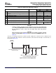
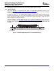
As illustrated in Figure 7-1 , the standoff height specification for this device (between 0.050 mm and
0.150 mm) is measured from the seating plane established by the three lowest package pins to the lowest
point on the package body. Due to warpage, the lowest point on the package body is located in the center
of the package at the exposed thermal pad.
Using this definition of standoff height provides the correct result for determining the correct solder paste
thickness. According to TI's PowerPAD Thermally Enhanced Package Technical Brief (literature number
SLMA002), the recommended range of solder paste thickness for this package is between 0.152 mm and
0.178 mm.
Figure 7-1. Standoff Height Measurement on 144-Pin RFP Package
108 Mechanical Data Submit Documentation Feedback