
Stereo System User Manual


www.ti.com
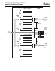
3.3 Peripheral Pin Multiplexing Control
TMS320C6727, TMS320C6726, TMS320C6722
Floating-Point Digital Signal Processors
SPRS268E – MAY 2005 – REVISED JANUARY 2007
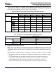
Table 3-3 lists the options for configuring the SPI1, McASP0, and McASP1 pins. Note that there are
additional finer grain options when selecting which McASP controls the particular AXR serial data pins but
these options are not listed here and can be made on a pin by pin basis.
Table 3-3. Options for Configuring SPI1, McASP0, and McASP1 Data Pins
CONFIGURATION
OPTION 1 OPTION 2 OPTION 3 OPTION 4 OPTION 5
PERIPHERAL SPI1 5-pin mode 4-pin mode 4-pin mode 3-pin mode disabled
McASP0 11 12 12 13 16
(max data pins)
McASP1 4 4 4 4 6
(max data pins)
PINS AXR0[5]/ SPI1_SCS SPI1_SCS AXR0[5] AXR0[5] AXR0[5]
SPI1_SCS
AXR0[6]/ SPI1_ENA AXR0[6] SPI1_ENA AXR0[6] AXR0[6]
SPI1_ENA
AXR0[7]/ SPI1_CLK SPI1_CLK SPI1_CLK SPI1_CLK AXR0[7]
SPI1_CLK
AXR0[8]/AXR1[5]/ SPI1_SOMI SPI1_SOMI SPI1_SOMI SPI1_SOMI AXR0[8] or AXR1[5]
SPI1_SOMI
AXR0[9]/AXR1[4]/ SPI1_SIMO SPI1_SIMO SPI1_SIMO SPI1_SIMO AXR0[9] or AXR1[4]
SPI1_SIMO
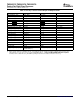
Table 3-4 lists the options for configuring the shared EMIF and UHPI pins.
Table 3-4. Options for Configuring EMIF and UHPI (C6727 Only)
CONFIGURATION
OPTION 1 OPTION 2
PERIPHERAL UHPI Multiplexed Address/Data Mode, Fullword, or Non-Multiplexed Address/Data Mode
Half-Word Fullword
EMIF 32-bit EMIF Data 16-bit EMIF Data
PINS EM_D[31:16]/ EM_D[31:16] UHPI_HA[15:0]
UHPI_HA[15:0]
While Section 3.2 describes at a high level the most common pin multiplexing options, the control of pin
multiplexing is largely determined on an individual pin-by-pin basis. Typically, each peripheral that shares
a particular pin has internal control registers to determine the pin function and whether it is an input or an
output.
The C672x device determines whether a particular pin is an input or output based upon the following
rules:
• The pin will be configured as an output if it is configured as an output in any of the peripherals sharing
the pin.
• It is recommended that only one peripheral configure a given pin as an output. If more than one
peripheral does configure a particular pin as an output, then the output value is controlled by the
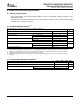
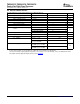
peripheral with highest priority for that pin. The priorities for each pin are given in Table 3-5 .
• The value input on the pin is passed to all peripherals sharing the pin for input simultaneously.
Submit Documentation Feedback Device Configurations 31