
Stereo System User Manual


www.ti.com
4.12.3 UHPI Electrical Data/Timing
TMS320C6727, TMS320C6726, TMS320C6722
Floating-Point Digital Signal Processors
SPRS268E – MAY 2005 – REVISED JANUARY 2007
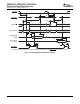
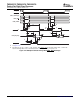
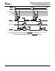
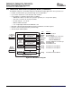
4.12.3.1 Universal Host-Port Interface (UHPI) Read and Write Timing
Table 4-15 and Table 4-16 assume testing over recommended operating conditions (see Figure 4-21
through Figure 4-24 ).
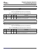
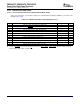
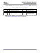
Table 4-15. UHPI Read and Write Timing Requirements
(1) (2)
NO. MIN MAX UNIT
9 t
su(HASL-DSL)
Setup time, UHPI_HAS low before DS falling edge 5 ns
10 t
h(DSL-HASL)
Hold time, UHPI_HAS low after DS falling edge 2 ns
11 t
su(HAD-HASL)
Setup time, HAD valid before UHPI_HAS falling edge 5 ns
12 t
h(HASL-HAD)
Hold time, HAD valid after UHPI_HAS falling edge 5 ns
13 t
w(DSL)
Pulse duration, DS low 15 ns
14 t
w(DSH)
Pulse duration, DS high 2P ns
15 t
su(HAD-DSL)
Setup time, HAD valid before DS falling edge 5 ns
16 t
h(DSL-HAD)
Hold time, HAD valid after DS falling edge 5 ns
17 t
su(HD-DSH)
Setup time, HD valid before DS rising edge 5 ns
18 t
h(DSH-HD)
Hold time, HD valid after DS rising edge 0 ns
37 t
su(HCSL-DSL)
Setup time, UHPI_HCS low before DS falling edge 0 ns
38 t
h(HRDYH-DSL)
Hold time, DS low after UHPI_HRDY rising edge 1 ns
(1) P = SYSCLK2 period
(2) DS refers to HSTROBE. HD refers to UHPI_HD[31:0]. HDS refers to UHPI_HDS[1] or UHPI_HDS[2]. HAD refers to UHPI_HCNTL[0],
UHPI_HCNTL[1], UHPI_HHWIL, and UHPI_HR W.
Peripheral and Electrical Specifications62 Submit Documentation Feedback