
Digital Media System-on-Chip (DMSoC) Product Preview

www.ti.com
PRODUCT PREVIEW
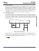
5.5.2 MXI2 (27-MHz) Oscillator (optional oscillator)
Crystal
27MHz
C1 C2
MXI2
MXO2 V
SS_MX2
L1
V
DDA_PLL2
V
SSA_PLL2
0.1 F
1 F
C
L
C
1
C
2
(C
1
C
2
)
TMS320DM355
Digital Media System-on-Chip (DMSoC)
SPRS463A – SEPTEMBER 2007 – REVISED SEPTEMBER 2007
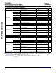
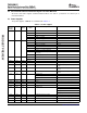
Table 5-3. Switching Characteristics Over Recommended Operating Conditions for 24-MHz System
Oscillator
PARAMETER MIN TYP MAX UNIT
Start-up time (from power up until oscillating at stable frequency) 4 ms
Oscillation frequency 24 or 36 MHz
ESR 60 Ω
Frequency stability +/-50 ppm
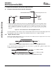
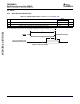
The MXI2 (27 MHz) oscillator provides an optional reference clock for the 's VPSS module. The on-chip
oscillator requires an external 27-MHz crystal connected across the MXI2 and MXO2 pins, along with two
load capacitors, as shown in Figure 5-6 . The external crystal load capacitors must be connected only to
the 27-MHz oscillator ground pin (V
SS_MX2
). Do not connect to board ground (V
SS
). Also, the PLL power
pin (V
DDA_PLL2
) should be connected to the power supply through a ferrite bead, L1 in the example circuit
shown in Figure 5-6 .
Figure 5-6. MXI2 (27-MHz) System Oscillator
The load capacitors, C1 and C2, should be chosen such that the equation is satisfied (typical values are
C1 = C2 = 10 pF). CL in the equation is the load specified by the crystal manufacturer. All discrete
components used to implement the oscillator circuit should be placed as close as possible to the
associated oscillator pins (MXI and MXO) and to the V
SS_MX2
pin.
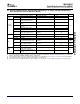
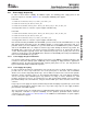
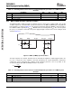
Table 5-4. Switching Characteristics Over Recommended Operating Conditions for 27-MHz System
Oscillator
PARAMETER MIN TYP MAX UNIT
Start-up time (from power up until oscillating at stable frequency) 4 ms
Oscillation frequency 27 MHz
ESR 60 Ω
Frequency stability +/-50 ppm
Peripheral Information and Electrical Specifications100 Submit Documentation Feedback