
Digital Media System-on-Chip (DMSoC) Product Preview

www.ti.com
PRODUCT PREVIEW
23
19
18
22
20
21
17
18
28
Stop Start Repeated
Start
Stop
SDA
SCL
16
TMS320DM355
Digital Media System-on-Chip (DMSoC)
SPRS463A – SEPTEMBER 2007 – REVISED SEPTEMBER 2007
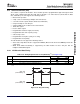
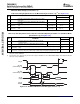
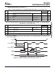
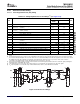
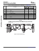
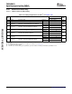
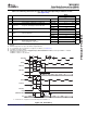
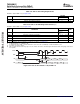
Table 5-34. Switching Characteristics for I2C Timings
(1)
(see Figure 5-40 )
DM355
STANDARD
NO. PARAMETER FAST MODE UNIT
MODE
MIN MAX MIN MAX
16 t
c(SCL)
Cycle time, SCL 10 2.5 μ s
Delay time, SCL high to SDA low (for a repeated START
17 t
d(SCLH-SDAL)
4.7 0.6 μ s
condition)
Delay time, SDA low to SCL low (for a START and a repeated
18 t
d(SDAL-SCLL)
4 0.6 μ s
START condition)
19 t
w(SCLL)
Pulse duration, SCL low 4.7 1.3 μ s
20 t
w(SCLH)
Pulse duration, SCL high 4 0.6 μ s
21 t
d(SDAV-SCLH)
Delay time, SDA valid to SCL high 250 100 ns
22 t
v(SCLL-SDAV)
Valid time, SDA valid after SCL low (For I2C devices) 0 0 0.9 μ s
Pulse duration, SDA high between STOP and START
23 t
w(SDAH)
4.7 1.3 μ s
conditions
28 t
d(SCLH-SDAH)
Delay time, SCL high to SDA high (for STOP condition) 4 0.6 μ s
29 C
p
Capacitance for each I2C pin 10 10 pF
(1) C
b
= total capacitance of one bus line in pF. If mixed with HS-mode devices, faster fall-times are allowed.
CAUTION
The DM355 I
2
C pins use a standard ± 4-mA LVCMOS buffer, not the slow I/OP buffer
defined in the I
2
C specification. Series resistors may be necessary to reduce noise at
the system level.
Figure 5-40. I2C Transmit Timings
136 Peripheral Information and Electrical Specifications Submit Documentation Feedback