
Digital Media System-on-Chip (DMSoC) Product Preview

www.ti.com
PRODUCT PREVIEW
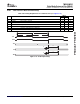
5.17 Real Time Out (RTO)
5.17.1 RTO Electrical/Timing Data
RTO0/1/2/3
1
3
3
2
4
TINT12/TINT34
(Timer3)
4
4
INVALID
INVALID
INVALID
VALID
VALID
VALID
RTO0
4
INVALID VALID
RTO1
RTO2
RTO3
TMS320DM355
Digital Media System-on-Chip (DMSoC)
SPRS463A – SEPTEMBER 2007 – REVISED SEPTEMBER 2007
The Real Time Out (RTO) peripheral supports the following features:
• Four separate outputs
• Trigger on Timer3 event
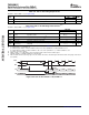
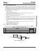
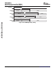
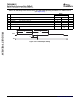
Table 5-47. Switching Characteristics Over Recommended Operating Conditions for RTO Outputs (see
Figure 5-49 and Figure 5-50 )
DM355
NO. PARAMETER UNIT
MIN MAX
1 t
w(RTOH)
Pulse duration, RTOx high P ns
2 t
w(RTOL)
Pulse duration, RTOx low P ns
3 t
t(RTO)
Transition time, RTOx .1P ns
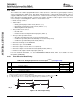
4 t
d(TIMER3-RTOV)
Delay time, Timer 3 (TINT12 or TINT34) trigger event to RTOx valid 10 ns
Figure 5-49. RTO Output Timing
Figure 5-50. RTO Output Delay Timing
Submit Documentation Feedback Peripheral Information and Electrical Specifications 147