
Digital Media System-on-Chip (DMSoC) Product Preview

www.ti.com
PRODUCT PREVIEW
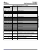
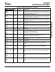
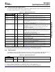
2.4.7 Universal Serial Bus (USB) Interface
2.4.8 Audio Interfaces
TMS320DM355
Digital Media System-on-Chip (DMSoC)
SPRS463A – SEPTEMBER 2007 – REVISED SEPTEMBER 2007
The Universal Serial Bus (USB) interface supports the USB2.0 High-Speed protocol and includes dual-role
Host/Slave support. However, no charge pump is included.
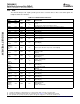
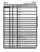
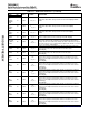
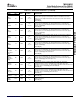
Table 2-13. USB Terminal Functions
TERMINAL
TYPE
(1)
OTHER
(2) (3)
DESCRIPTION
NAME NO.
USB D+ (differential signal pair).
USB_DP A7 A I/O/Z V
DDA33_USB
When USB is not used, this signal should be connected to V
SS_USB
.
USB D- (differential signal pair).
USB_DM A6 A I/O/Z V
DDA33_USB
When USB is not used, this signal should be connected to V
SS_USB
.
USB reference current output
Connect to VSS_USB_REF via 10K ohm , 1% resistor placed as close to the
USB_R1 C7 A I/O/Z
device as possible.
When USB is not used, this signal should be connected to V
SS_USB
.
USB operating mode identification pin
For Device mode operation only, pull up this pin to VDD with a 1.5K ohm resistor.
For Host mode operation only, pull down this pin to ground (VSS) with a 1.5K
USB_ID D5 A I/O/Z V
DDA33_USB
ohm resistor.
If using an OTG or mini-USB connector, this pin will be set properly via the
cable/connector configuration.
When USB is not used, this signal should be connected to V
SS_USB
.
For host or device mode operation, tie the VBUS/USB power signal to the USB
connector.
USB_VBUS E5 A I/O/Z V
DD
When used in OTG mode operation, tie VBUS to the external charge pump and
to the VBUS signal on the USB connector.
When the USB is not used, tie VBUS to Vss_USB.
Digital output to control external 5 V supply
USB_DRVVBUS C5 O/Z V
DD
When USB is not used, this signal should be left as a No Connect.
USB Ground Reference
V
SS_USB_REF
C8 GND V
DD
Connect directly to ground and to USB_R1 via 10K ohm, 1% resistor placed as
close to the device as possible
Analog 3.3 V power USBPHY
V
DDA33_USB
J8 PWR V
DD
When USB is not used, this signal should be connected to V
SS_USB
.
Common mode 3.3 V power for USB PHY (PLL)
V
DDA33_USB_PLL
B6 PWR V
DD
When USB is not used, this signal should be connected to V
SS_USB
.
Analog 1.3 V power for USB PHY
V
DDA13_USB
H7 PWR V
DD
When USB is not used, this signal should be connected to V
SS_USB
.
Digital 1.3 V power for USB PHY
V
DDD13_USB
C6 PWR V
DD
When USB is not used, this signal should be connected to V
SS_USB
.
(1) I = Input, O = Output, Z = High impedance, S = Supply voltage, GND = Ground, A = Analog signal.
(2) Specifies the operating I/O supply voltage for each signal. See Section 5.3 , Power Supplies for more detail.
(3) PD = pull-down, PU = pull-up. (To pull up a signal to the opposite supply rail, a 1 k Ω resistor should be used.)
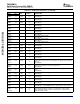
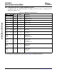
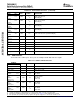
The DM355 includes two Audio Serial Ports (ASP ports), which are backward compatible with other TI
ASP serial ports and provide I2S audio interface. One interface is multiplexed with GIO signals.
Table 2-14. ASP Terminal Functions
TERMINAL
TYPE
(1)
OTHER
(2) (3)
DESCRIPTION
NAME NO.
ASP0_CL
ASP0: Receive Clock
KR/ F17 I/O/Z V
DD
GIO: GIO[026]
GIO026
(1) I = Input, O = Output, Z = High impedance, S = Supply voltage, GND = Ground, A = Analog signal.
(2) Specifies the operating I/O supply voltage for each signal. See Section 5.3 , Power Supplies for more detail.
(3) PD = pull-down, PU = pull-up. (To pull up a signal to the opposite supply rail, a 1 k Ω resistor should be used.)
Submit Documentation Feedback Device Overview 29