
Digital Media System-on-Chip (DMSoC) Product Preview

www.ti.com
PRODUCT PREVIEW
3.14 64-Bit Crossbar Architecture
3.14.1 Crossbar Connections
3.14.2 EDMA Controller
TMS320DM355
Digital Media System-on-Chip (DMSoC)
SPRS463A – SEPTEMBER 2007 – REVISED SEPTEMBER 2007
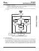
The DM355 uses a 64-bit crossbar architecture to control access between device processors, subsystems
and peripherals. It includes an EDMA Controller consisting of a DMA Transfer Controller (TC) and a DMA
Channel Controller (CC). The TC provides two DMA channels for transfer between slave peripherals. The
CC provides a user and event interface to the EDMA system. It includes up to 64 event channels to which
all system synchronization events can be mapped and 8 auto submit “quick” channels (QDMA). In most
ways, these channels are identical. A channel refers to a specific ‘event’ that can cause a transfer to be
submitted to the TC as a Transfer Request.
There are five transfer masters (TCs have separate read and write connections) connected to the
crossbar; ARM, the Video Processing Sub-system (VPSS), the master peripherals (USB), and two EDMA
transfer controllers. These can be connected to four separate slave ports; ARM, the DDR EMIF, and CFG
bus peripherals. Not all masters may connect to all slaves. Connection paths are indicated by √ at
intersection points shown in Table 3-18
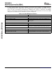
Table 3-18. Crossbar Connection Matrix
Slave Module
DMA Master ARM Internal MPEG/JPEG Config Bus Registers and DDR EMIF Memory
Memory Co-processor Memory
Memory
ARM √ √ √ √
VPSS √
DMA Master Peripherals (USB) √ √
EDMA3TC0 √ √ √ √
EDMA3TC1 √ √ √ √
The EDMA controller handles all data transfers between memories and the device slave peripherals on
the DM355 device. These are summarized as follows:
• Transfer to/from on-chip memories
– ARM program/data RAM
– MPEG/JPEG Co-processor memory
• Transfer to/from external storage
– DDR2 / mDDR SDRAM
– Asynchronous EMIF
– OneNAND flash
– NAND flash
– Smart Media, SD, MMC, xD media storage
• Transfer to/from peripherals
– ASP
– SPI
– I2C
– PWM
– RTO
– GPIO
– Timer/WDT
– UART
– MMC/SD
Submit Documentation Feedback Detailed Device Description 87