
Digital Media System-on-Chip (DMSoC) Product Preview

www.ti.com
PRODUCT PREVIEW
TMS320DM355
Digital Media System-on-Chip (DMSoC)
SPRS463A – SEPTEMBER 2007 – REVISED SEPTEMBER 2007
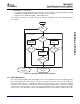
DMA Channels: Can be triggered by: " External events (for example, ASP TX Evt and RX Evt), " Software
writing a '1' to the given bit location, or channel, of the Event Set register, or, " Chaining to other DMAs.
QDMA: The Quick DMA (QDMA) function is contained within the CC. DM355 implements 8 QDMA
channels. Each QDMA channel has a selectable PaRAM entry used to specify the transfer. A QDMA
transfer is submitted immediately upon writing of the "trigger" parameter (as opposed to the occurrence of
an event as with EDMA). The QDMA parameter RAM may be written by any Config bus master through
the Config Bus and by DMAs through the Config Bus bridge.
QDMA Channels: Triggered by a configuration bus write to a designated 'QDMA trigger word'. QDMAs
allow a minimum number of linear writes (optimized for GEM IDMA feature) to be issued to the CC to
force a series of transfers to take place.
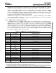
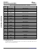
3.14.2.1 EDMA Channel Synchronization Events
The EDMA supports up to 64 EDMA channels which service peripheral devices and external memory.
Table 3-19 lists the source of EDMA synchronization events associated with each of the programmable
EDMA channels. For the device, the association of an event to a channel is fixed; each of the EDMA
channels has one specific event associated with it. These specific events are captured in the EDMA event
registers (ER, ERH) even if the events are disabled by the EDMA event enable registers (EER, EERH).
For more detailed information on the EDMA module and how EDMA events are enabled, captured,
processed, linked, chained, and cleared, etc., see the Document Support section for the Enhanced Direct
Memory Access (EDMA) Controller Reference Guide.
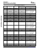
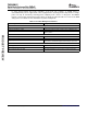
Table 3-19. EDMA Channel Synchronization Events
(1) (2)
EDMA
EVENT NAME EVENT DESCRIPTION
CHANNEL
0 TIMER3: TINT6 Timer 3 Interrupt (TINT6) Event
1 TIMER3 TINT7 Timer 3 Interrupt (TINT7) Event
2 ASP0: XEVT ASP0 Transmit Event
3 ASP0: REVT ASP0 Receive Event
4 VPSS: EVT1 VPSS Event 1
5 VPSS: EVT2 VPSS Event 2
6 VPSS: EVT3 VPSS Event 3
7 VPSS: EVT4 VPSS Event 4
ASP1: XEVT or TIMER2:
8 ASP1 Transmit Event or Timer 2 interrupt (TINT4) Event
TINT4
ASP1: REVT or TIMER2:
9 ASP1 Receive Event or Timer 2 interrupt (TINT5) Event
TINT5
10 SPI2: SPI2XEVT SPI2 Transmit Event
11 SPI2: SPI2REVT SPI2 Receive Event
12 Reserved
13 Reserved
14 SPI1: SPI1XEVT SPI1 Transmit Event
15 SPI1: SPI1REVT SPI1 Receive Event
16 SPI0: SPI0XEVT SP0I Transmit Event
17 SPI0: SPI0REVT SPI0 Receive Event
18 UART0: URXEVT0 UART 0 Receive Event
19 UART0: UTXEVT0 UART 0 Transmit Event
20 UART1: URXEVT1 UART 1 Receive Event
(1) In addition to the events shown in this table, each of the 64 channels can also be synchronized with the transfer completion or
intermediate transfer completion events. For more detailed information on EDMA event-transfer chaining, see the Document Support
section for the Enhanced Direct Memory Access (EDMA) Controller Reference Guide.
(2) The total number of EDMA events in DM355 exceeds 64, which is the maximum value of the EDMA module. Therefore, several events
are multiplexed and you must use the register EDMA_EVTMUX in the System Control Module to select the event source for multiplexed
events. Refer to the ARM Subsystem Guide for more information on the System Control Module register EDMA_EVTMUX.
Submit Documentation Feedback Detailed Device Description 89