
User Guide

www.ti.com
1.4 Industry Standard(s) Compliance Statement
2 Peripheral Architecture
2.1 Clock Control
2.2 Memory Map
2.3 Signal Descriptions
Peripheral Architecture
The EMAC peripheral conforms to the IEEE 802.3 standard, describing the Carrier Sense Multiple Access
with Collision Detection (CSMA/CD) Access Method and Physical Layer specifications. The IEEE 802.3
standard has also been adopted by ISO/IEC and re-designated as ISO/IEC 8802-3:2000(E).
In difference from this standard, the EMAC peripheral does not use the Transmit Coding Error signal
MTXER. Instead of driving the error pin when an underflow condition occurs on a transmitted frame, the
EMAC intentionally generates an incorrect checksum by inverting the frame CRC, so that the transmitted
frame is detected as an error by the network.
This section discusses the architecture and basic function of the EMAC peripheral.
The frequencies for the transmit and receive clocks are fixed by the IEEE 802.3 specification as:
• 2.5 MHZ at 10 Mbps
• 25 MHZ at 100 Mbps
All EMAC logic is clocked synchronously with the PLL1/6 peripheral clock, except for the Ethernet MII
synchronization logic.
The transmit and receive clock sources are provided from the external PHY via the MTCLK and MRCLK
pins. These clocks are inputs to the EMAC module and operate at 2.5 MHZ in 10-Mbps mode, and at 25
MHZ in 100-Mbps mode. For timing purposes, data is transmitted and received with respect to MTCLK
and MRCLK, respectively.
The MDIO clock is based on a divide-down of the peripheral clock (PLL1/6) specified to run up to 2.5
MHZ, although typical operation would be 1.0 MHZ. Since the peripheral clock frequency is variable
(PLL1/6), the application software or driver controls the divide-down amount.
The EMAC peripheral includes internal memory that is used to hold information about the Ethernet
packets received and transmitted. This internal RAM is 2K × 32 bits in size. Data can be written to and
read from the EMAC internal memory by either the EMAC or the CPU. It is used to store buffer descriptors
that are 4-words (16-bytes) deep. This 8K local memory holds enough information to transfer up to 512
Ethernet packets without CPU intervention.
The packet buffer descriptors can also be placed in the internal processor memory (L2), or in EMIF
memory (DDR). There are some tradeoffs in terms of cache performance and throughput when
descriptors are placed in the system memory, versus when they are placed in the EMAC’s internal
memory. Cache performance is improved when the buffer descriptors are placed in internal memory.
However, the EMAC throughput is better when the descriptors are placed in the local EMAC RAM.
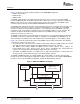
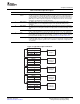
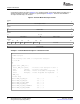
Figure 2 shows a device with integrated EMAC and MDIO interfaced via a MII connection in a typical
system. The EMAC module does not include a transmit error (MTXER) pin. In the case of transmit error,
CRC inversion is used to negate the validity of the transmitted frame.
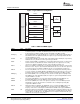
The individual EMAC and MDIO signals for the MII interface are summarized in Table 1 . For more
information, refer to either the IEEE 802.3 standard or ISO/IEC 8802-3:2000(E).
SPRU941A – April 2007 Ethernet Media Access Controller (EMAC)/ 13
Management Data Input/Output (MDIO)
Submit Documentation Feedback