TMS320DM6446 DVEVM v2.
IMPORTANT NOTICE Texas Instruments Incorporated and its subsidiaries (TI) reserve the right to make corrections, modifications, enhancements, improvements, and other changes to its products and services at any time and to discontinue any product or service without notice. Customers should obtain the latest relevant information before placing orders and should verify that such information is current and complete.
EVALUATION BOARD/KIT IMPORTANT NOTICE Texas Instruments (TI) provides the enclosed product(s) under the following conditions: This evaluation board/kit is intended for use for ENGINEERING DEVELOPMENT, DEMONSTRATION, OR EVALUATION PURPOSES ONLY and is not considered by TI to be a finished end-product fit for general consumer use. Persons handling the product(s) must have electronics training and observe good engineering practice standards.
FCC Warning This evaluation board/kit is intended for use for ENGINEERING DEVELOPMENT, DEMONSTRATION, OR EVALUATION PURPOSES ONLY and is not considered by TI to be a finished end-product fit for general consumer use. It generates, uses, and can radiate radio frequency energy and has not been tested for compliance with the limits of computing devices pursuant to part 15 of FCC rules, which are designed to provide reasonable protection against radio frequency interference.
This is a draft version printed from file: pref.fm on 12/18/08 Preface About This Guide The DVEVM (Digital Video Evaluation Module) kit is an evaluation platform that showcases the DM644x architecture and lets users evaluate the power and performance of the DM644x as a multimedia engine. This guide gives you overview information about the board and the software provided with the board. It is intended to be used as an introductory document for the DVEVM. Other documents provide more in-depth information.
Notational Conventions Notational Conventions This document uses the following conventions: ❏ Program listings, program examples, and interactive displays are shown in a mono-spaced font. Examples use bold for emphasis, and interactive displays use bold to distinguish commands that you enter from items that the system displays (such as prompts, command output, error messages, etc.). ❏ Square brackets ( [ and ] ) identify an optional parameter.
This is a draft version printed from file: davinci_gsgTOC.fm on 12/18/08 Contents 1 DVEVM Overview . . . . . . . . . . . . . . . . . . . . . . . . . . . . . . . . . . . . . . . . . . . . . . . . . . . . . . . . . . .1-1 This chapter introduces the DVEVM (Digital Video Evaluation Module) kit. 1.1 Welcome! . . . . . . . . . . . . . . . . . . . . . . . . . . . . . . . . . . . . . . . . . . . . . . . . . . . . . . . . . . . .1-2 1.2 What’s in this Kit? . . . . . . . . . . . . . . . . . . . . . . . . . . . .
Contents 4.4 4.5 4.6 4.7 4.8 4.9 4.10 4.11 A Additional Procedures . . . . . . . . . . . . . . . . . . . . . . . . . . . . . . . . . . . . . . . . . . . . . . . . . . . . . . A-1 This appendix describes optional procedures you may use depending on your setup and specific needs. A.1 A.2 A.3 A.4 A.5 A.6 viii 4.3.5 Exporting a Shared File System for Target Access . . . . . . . . . . . . . . . . . . . 4-9 4.3.6 Testing the Shared File System . . . . . . . . . . . . . . . . . . . . . . . . . . . . . . . . .
Chapter 1 DVEVM Overview This chapter introduces the DVEVM (Digital Video Evaluation Module) kit. Topic Page 1.1 Welcome! . . . . . . . . . . . . . . . . . . . . . . . . . . . . . . . . . . . . . . . . . . . . . . . 1–2 1.2 What’s in this Kit? . . . . . . . . . . . . . . . . . . . . . . . . . . . . . . . . . . . . . . . . 1–3 1.3 What’s on the Board? . . . . . . . . . . . . . . . . . . . . . . . . . . . . . . . . . . . . . 1–4 1.4 What’s Next? . . . . . . . . . . . . . . . . . . . . . . . . . . .
Welcome! 1.1 Welcome! Your new DVEVM (Digital Video Evaluation Module) kit will allow you to evaluate TI’s new DaVinciTM Technology and the DM644x architecture. This technology brings together system-solution components tailored for efficient and compelling digital video and audio.
What’s in this Kit? 1.2 What’s in this Kit? Your DVEVM kit contains the following hardware items. Section 2.1, Setting Up the Hardware tells how to connect these components. ❏ EVM Board. This board contains a DaVinci TMS320DM6446 dualcore device with an ARM9 and C64+ DSP for development of applications that use both a general-purpose processor and an accelerated DSP processor. ❏ Hard Disk Drive. The hard drive provided with the EVM is a 2.5" Spinpoint drive with 40 GB of storage.
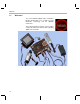
What’s on the Board? 1.3 What’s on the Board? The EVM comes loaded with peripherals your multimedia applications may need to make use of. The hard drive on the board also comes preloaded with demonstration software. The following block diagram shows the major hardware components. Diagram provided courtesy of Spectrum Digital Inc. Figure 1–1 EVM Hardware Block Diagram For more information about the EVM hardware, see the DaVinci EVM website at http://c6000.spectrumdigital.com/davincievm.
What’s Next? 1.4 What’s Next? To get started evaluating the DVEVM kit and developing applications for the DM644x, begin by using this Getting Started guide. It will step you through connecting the hardware, testing the software, and beginning to develop applications. When you are ready for more information about DaVinci Technology and the DM644x architecture, see the following: ❏ Spectrum Digital website: http://c6000.spectrumdigital.
1-6
Chapter 2 EVM Hardware Setup This chapter tells you how to set up the EVM hardware. Topic Page 2.1 Setting Up the Hardware . . . . . . . . . . . . . . . . . . . . . . . . . . . . . . . . . . . 2–2 2.2 Connecting to a Console Window . . . . . . . . . . . . . . . . . . . . . . . . . . .
Setting Up the Hardware 2.1 Setting Up the Hardware To set up the hardware provided with the EVM, use the steps in the sections that follow. You may skip sections if you do not need to access a particular peripheral. For example, if you do not need to use the serial cable, skip that section. 1) The EVM is sensitive to static discharges. Use a grounding strap or other device to prevent damaging the board. Be sure to connect communication cables before applying power to any equipment.
Setting Up the Hardware 4) Connect the red and white audio cables to the EVM Audio Output and the LCD display R/L Audio Input jacks as shown below: 5) Connect the BNC-to-RCA connector to the coax cable. Then connect the coax cable to the video camera and the EVM Video Input. 6) Connect the power jack for the video camera. To be ESD safe, do not plug in the other end of the camera power cord until the later step that instructs you to do so. See Section A.
Setting Up the Hardware 7) Connect the microphone to the EVM. 8) Connect the power cable to the EVM power jack on the board. To be ESD safe, do not plug in the other end of the cable yet. 9) If you will use the Ethernet connection, connect the Ethernet cable to the Ethernet Port on the EVM and to an Ethernet network port. Note that the U-Boot bootargs must include "ip=dhcp" to enable the network connection.
Setting Up the Hardware 10) If you plan to use the UART port for a console window, connect the RS-232 null modem cable to the EVM UART port and a COM port on your host Linux workstation. See Section 2.2, Connecting to a Console Window for more about using a console window. 11) Plug in the LCD display to a power supply. 12) Plug in the NTSC/PAL video camera to a power supply. 13) Connect the power cable to the EVM power jack on the board.
Connecting to a Console Window 2.2 Connecting to a Console Window You can open a console window that allows you to watch and interrupt EVM boot messages by following these steps: 1) Connect a serial cable between the serial port on the EVM and the serial port (for example, COM1) on a PC.
Chapter 3 Running the Demonstration Software This chapter explains how to run the software demos provided with the DVEVM kit. Topic Page 3.1 Default Boot Configuration. . . . . . . . . . . . . . . . . . . . . . . . . . . . . . . . . 3–2 3.2 Starting the Standalone Demos . . . . . . . . . . . . . . . . . . . . . . . . . . . . . 3–2 3.3 Running the Standalone Demos . . . . . . . . . . . . . . . . . . . . . . . . . . . . 3–4 3.4 Running the Demos from the Command Line . . . . . . . . . . . . . . . .
Default Boot Configuration 3.1 Default Boot Configuration Out of the box, the EVM boots from flash and starts the demos automatically after a few seconds when you power up the board. It does not require an NFS mount or a TFTP server to run the standard demos. Note: The default U-Boot bootargs definition sets "ip=off", which disables the Ethernet connection. The out-of-the-box boot parameters are listed in Section A.4.1.
Starting the Standalone Demos running. Otherwise you will see error messages raised when device drivers fail to open. Once the EVM board has booted, the display should show a picture of the remote control. You use the IR remote to control the demos. The order of the buttons on the actual remote may be different from the picture; if your remote looks different, find the buttons with the same labels on your remote.
Running the Standalone Demos 3.3 Running the Standalone Demos 1) Press "Play" or "OK" on the remote to move from the remote control diagram to the main menu screen, which looks like this: The Encode + Decode demo allows you to record and playback video. The Encode demo records audio/speech and video in the formats you select. The Decode demo plays audio/speech and video files you select. The Third-Party Menu can be used to add additional demos (see Section A.
Running the Standalone Demos 5) Use the left and right arrows to cycle through the options until the setting you want is shown. 6) Press "Play" to begin the Encode+Decode and Decode demos. Press "Rec" (record) twice to begin the Encode demo. 7) While the demo runs, data about the settings, processor load, and rates are shown. Static settings are on the right. Dynamic data reporting is on the left.
Running the Standalone Demos 3.3.2 About the Encode + Decode Demo The Encode + Decode demo allows you to record and playback video. Video comes from the camera, is encoded, then decoded, and then sent to the LDC display. The Encode + Decode does only video processing; it does not encode and decode audio or speech. The supported video algorithm is H.264 Baseline Profile (.264 file extension).
Running the Standalone Demos 3.3.3 About the Encode Demo Like the Encode + Decode demo, the Encode demo also encodes video. In addition, it also encodes speech. The speech source is the microphone. The encoded data is written to files on the EVM’s hard disk drive. The possible filenames are demo.264, demo.mpeg4, demompeg4.g711, and demo264.g711. Older versions of these files are overwritten as needed.
Running the Standalone Demos Table 3–2 IR Remote Buttons for Encode Demo IR Remote Button Mode Action Performed Info/Select Setup Show / hide block diagram for demo Info/Select Run Toggle information display Left/Right Run Change information transparency level (There is no display for encode demo behind the information.) Pause Run Pause demo (press Record to resume) Stop Setup / Run Return to previous screen The application runs on the ARM using Linux.
Running the Demos from the Command Line The supported video algorithms are MPEG4 (.mpeg4 file extension), H.264 (.264 file extension) and MPEG2 (.m2v file extension). The supported audio algorithm is AAC (.aac file extension). The supported speech algorithm is G.711 (.g711 file extension).
Running the Demos from the Command Line 3) Move to the appropriate directory on the target using the following command. (See Section 4.1.1 for the meanings of command prompts shown in this document.) Target $ cd /opt/dvsdk/dm6446 4) Before running demo applications from the command line, the CMEM and accelerator kernel modules must be loaded. ■ Use "lsmod" to see if they are loaded.
Running the Network Demo 3.5 Running the Network Demo As an example of standard TCP/IP networking support, the DVEVM examples include a small HTTP web server. This web server is started on the GPP-side as part of the Linux startup sequence. It configured to service requests from web browsers on the standard TCP/IP port 80. After the EVM board has booted, connect a PC to the same network to which the EVM board is connected.
3-12
Chapter 4 DVEVM Software Setup This chapter explains how to use the software provided with the DVEVM kit. Topic Page 4.1 Software Overview . . . . . . . . . . . . . . . . . . . . . . . . . . . . . . . . . . . . . . . 4–2 4.2 Preparing to Install . . . . . . . . . . . . . . . . . . . . . . . . . . . . . . . . . . . . . . . 4–5 4.3 Installing the Software . . . . . . . . . . . . . . . . . . . . . . . . . . . . . . . . . . . . 4–5 4.4 Setting Up the Build/Development Environment . . . . . . . . . .
Software Overview 4.1 Software Overview To begin developing applications, you need to install the DVEVM development environment. This chapter outlines the steps required to load the DVEVM software onto the development host. You will need the distribution disks or the files they contain to get started. The DaVinci software approach provides interoperable, optimized, production-ready video and audio codecs that leverage DSP and integrated accelerators.
Software Overview Texas Instruments, in agreement with MontaVista Software Inc., is providing a demonstration version of the Linux Professional Edition v5.0 embedded operating system and development tools. The base DVEVM kit includes this demonstration version. The demo version is a subset of what MontaVista provides with the full Professional Edition.
Software Overview 4.1.2 Software Components The following figure shows the software components used for application development with the DVEVM kit: VISA API Application I/O I/O I/O DMAI VISA API Codec Engine Operating System Adaptation Layer (OSAL) VID SPH IMG AUD Engine Server xDM API User Space Speech Codec Linux APIs CMEM Driver USB 2.
Preparing to Install 4.2 Preparing to Install On a host system, mount the DVEVM demonstration DVD and copy the following files to a temporary location with at least 2.3 GB available space. Since you can delete the installation files after installing the software, a directory like /tmp is recommended. ❏ mvl_5_0_demo_sys_setuplinux.bin (disk 1) ❏ mvl_5_0_0_demo_lsp_setuplinux_#_#_#_#.bin (disk 2) ❏ dvsdk_setuplinux_#_#_#_#.bin (disk 2) ❏ xdctools_setuplinux_#_#_#.
Installing the Software 4.3.1 Installing the Target Linux Software This section explains how to install Linux for use on the target board. This is a demonstration version of MontaVista Linux Pro v5.0. Note that separate versions of Linux are used by the target and your host Linux workstation. The following Linux host operating system is tested with the DVEVM: Red Hat Enterprise Linux v4 (Server Edition). To install the Linux software, follow these steps: 1) Log in as root on your host Linux workstation.
Installing the Software 4.3.2 Installing the DVSDK Software The DVSDK software includes Codec Engine components, DSP/BIOS Link, sample data files, xDAIS and xDM header files, and a contiguous memory allocator for Linux (CMEM). Note: The installers for DSP/BIOS and Code Generation Tools (codegen) have a different default installation location.
Installing the Software When the installer prompts for an installation location, do not use the default location. Instead, use the entire path to the dvsdk_#_# codegen directory. You will need to manually create the folder cg6x_6_#_#, where # represents part of the version number. For example: /home//dvsdk_#_#/cg6x_6_0_16. Remember to set the environment variable as directed by the installer.
Installing the Software 4.3.4 Installing the SoC Analyzer SoC Analyzer is a graphical tool that runs on a Windows development host and uses data collected from Linux, DSP/BIOS, and Codec Engine to provide system-level execution and performance analysis for debugging and profiling DVEVM software execution. Follow these instructions to install SoC Analyzer: 1) Insert the TI DVSDK software disk into the Windows development host PC. 2) Browse to the SoCAnalyzer/WinXP folder.
Installing the Software 4) Perform the following commands to create a copy of the target file system with permissions set for writing to the shared area as . Substitute your user name for . If you installed in a location other than /opt/mv_pro_5.0, use your location in the cp command. host $ cp -a /opt/mv_pro_5.0/montavista/pro/devkit/arm/v5t_le/target/* .
Installing the Software 4.3.6 Testing the Shared File System To test your NFS setup, follow these steps: 1) Get the IP address of your host Linux workstations as follows. Look for the IP address associated with the eth0 Ethernet port. host $ /sbin/ifconfig 2) Open a terminal emulation window to connect to the EVM board via RS-232 using the instructions in Section 2.2. If you have a Windows workstation, you can use HyperTerminal. If you have a Linux workstation, you might use Minicom.
Installing the Software See Section A.4, Alternate Boot Methods for information about booting with TFTP or NFS and using flash or the EVM’s hard drive. 4.3.7 Configuring the Boot Setup for PAL Video Users You can configure the EVM to select either the NTSC or PAL video standard during the default boot sequence. To select PAL, set switch 10 on the S3 (USER) user bank of switches to On. For NTSC, set this switch to Off.
Setting Up the Build/Development Environment These codecs are provided under a "for demonstration-only" license agreement. If you wish to use these codecs in a production development environment, you can go to the DVEVM Updates web site at http://www.ti.com/dvevmupdates to download the latest production versions, along with the appropriate license agreement. 4.
Building a New Linux Kernel 4) host $ arm_v5t_le-gcc hello.c -o hello Perform the following steps on the target board. You may use either the target's console window (Section 2.2) or a telnet session. 1) target $ cd /opt/hello 2) Run ./hello. The output should be: Buongiorno DaVinci! 4.
Building a New Linux Kernel 5) To modify the kernel options, you will need to use a configuration command such as "make menuconfig" or "make xconfig". To enable the MontaVista default kernel options, use the following command: host $ make ARCH=arm CROSS_COMPILE=arm_v5t_le- checksetconfig 6) If you want to enable Linux Trace for the SoC Analyzer, follow these substeps. Otherwise, skip to Step 7.
Rebuilding the DVEVM Software for the Target 4.6 Rebuilding the DVEVM Software for the Target To place demo files in the /opt/dvsdk/dm6446 directory, you need to rebuild the DVSDK software. To do this, follow these steps: 1) If you have not already done so, rebuild the Linux kernel as described in Section 4.5. 2) Change directory to dvsdk_#_#. 3) Edit the Rules.make file in the dvsdk_#_#. directory.
Booting the New Linux Kernel 5) You can test the rebuilt DVEVM software by booting your NFS file system and running the demos from the command line as described in Section 3.4. 4.7 Booting the New Linux Kernel After building the new kernel, in order to use it to boot the DaVinci board, you must transfer it to the board via TFTP. It is assumed you have completed the steps in Section 4.
Testing the Build Environment 4.8 Testing the Build Environment To test your DVSDK software installation, you can build one of the Codec Engine servers. This server is a DSP-side application. Building it tests the installation of DSP-side development components. To build the video_copy server, follow these steps: 1) Go to /home//dvsdk_#_#/codec_engine_#_#/examples and open the build_instructions.html file. 2) Follow the step-by-step instructions for building examples.
Using the Digital Video Test Bench (DVTB) 3) Copy the binaries "dvtb-d" and "dvtb-r" to /opt/dvsdk/dm6446 on the device’s target filesystem and run it there. It must be in the same directory as the DSP executables. For further details on the DVTB, see the following documents: ❏ Release Notes. /home//dvsdk_#_#/dvtb_#_#_#/docs/dvtb_release_notes.pdf ❏ User Guide.. /home//dvsdk_#_#/dvtb_#_#_#/docs/dvtb_user_guide.
Running The SoC Analyzer 4.10 Running The SoC Analyzer Built upon Texas Instruments' eXpressDSP data visualization technology (DVT), the SoC Analyzer simplifies debugging, analysis, and optimization of DVEVM applications.
Documentation for DSP-Side Development To run the SoC Analyzer, double-click the SoC Analyzer icon on the Windows Desktop or select it from the Windows Start menu under Texas Instruments. The SoC Analyzer comes with online help, which can be accessed from the SoC Analyzer Help menu (choose Help->Help Contents). Select the DM644x SoC Analyzer User Guide.
Documentation for DSP-Side Development Table 4-1. Component Documentation for DVSDK Components Title Location Section 4.
Appendix A Additional Procedures This appendix describes optional procedures you may use depending on your setup and specific needs. Topic Page A.1 Changing the Video Input/Output Methods. . . . . . . . . . . . . . . . . . . . A–2 A.2 Putting Demo Applications in the Third-Party Menu . . . . . . . . . . . . A–5 A.3 Setting Up a TFTP Server . . . . . . . . . . . . . . . . . . . . . . . . . . . . . . . . . . A–7 A.4 Alternate Boot Methods . . . . . . . . . . . . . . . . . . . . . . . . . . . . . . . . . .
Changing the Video Input/Output Methods A.1 Changing the Video Input/Output Methods The EVM can input video using the following methods: ❏ Composite [default] ❏ S-Video (best quality) In addition, there are three types of video output: ❏ Composite [default] (lowest quality) ❏ S-Video (medium quality) ❏ Component (best quality) There is a significant quality difference between the different inputs and outputs. However, the cables in the DVEVM kit support only composite video.
Changing the Video Input/Output Methods A.1.2 Using S-Video Output To switch to higher-quality S-Video output, follow these steps: 1) Unplug the composite video connector. Then, connect your S-Video connector to the S-Video output port, which is to the right of the currently-used composite video output port. S-Video OUT The DVEVM kit does not include an S-Video cable. In addition, you will need a video display with an S-Video input.
Changing the Video Input/Output Methods A.1.3 Using Component Video Output To switch to highest-quality component video output, follow these steps: 1) Connect your component video connectors to the connectors in a square on the far left of the board. Instead of connecting one connector as with composite video, connect the YPrPb connectors as shown here. Pr Pb Y The DVEVM kit does not include a 3-connector cable used for component (YPrPb) video.
Putting Demo Applications in the Third-Party Menu A.2 Putting Demo Applications in the Third-Party Menu You can add your own demos to the Third-Party Menu by following the steps in this section. Only four demos can be shown at once in the userinterface. If you add more than four demos, the first four in alphabetical order are shown. 1) Create the following files for your demo: ■ logo.jpg. This is the logo of the third party company which will be showed next to the demo description.
Putting Demo Applications in the Third-Party Menu uses relative references to access them. For example, the following directory structure might be used in the archive: |-|-| | |-`-- app.sh data |-- datafile1 `-- datafile2 logo.jpg readme.txt To check the format of the file you create, execute the following command in Linux. The result should say "gzip compressed data". file .tar.gz 3) Put your archive in the "thirdpartydemos" subdirectory of the target installation directory.
Setting Up a TFTP Server A.3 Setting Up a TFTP Server You can check to see if a TFTP server is set up with the following command: host $ rpm -q tftp-server If it is not set up, you can follow these steps: 1) If you have not yet installed MontaVista Linux Demo Edition (see Section 4.3.1), you can download a TFTP server for your Linux host from many locations on the Internet. Search for "tftp-server". 2) To install TFTP, use this command, where -#.
Alternate Boot Methods A.4 Alternate Boot Methods The default configuration for the EVM is to boot from flash with the file system on the EVM’s hard drive. The following are alternate ways you may want to boot the board: ❏ TFTP boot with hard drive file system (Section A.4.2) ❏ Flash boot with NFS file system (Section A.4.3) ❏ TFTP boot with NFS file system (Section A.4.4) Section 4.3.7 discusses booting in PAL mode vs. NTSC mode.
Alternate Boot Methods To boot in this mode, set the following parameters after you abort the automatic boot sequence: EVM # setenv bootcmd bootm 0x2050000 setenv bootcmd nboot 80700000 0 a0000;bootm EVM # setenv bootargs video=davincifb:vid0=720x576x16, 2500K:vid1=720x576x16,2500K:osd0=720x576x16,2025K davinci_enc_mngr.ch0_output=COMPOSITE davinci_enc_mngr.
Alternate Boot Methods A.4.3 Booting from Flash Using NFS File System To boot in this mode, set the following parameters after you abort the automatic boot sequence: EVM # setenv bootcmd 0x2050000 setenv bootcmd nboot 80700000 0 a0000;bootmEVM # setenv nfshost EVM # setenv rootpath EVM # setenv bootargs video=davincifb:vid0=720x576x16, 2500K:vid1=720x576x16,2500K:osd0=720x576x16,2025K davinci_enc_mngr.ch0_output=COMPOSITE davinci_enc_mngr.
Rebuilding DSP/BIOS Link The must match the file system that you set up on your workstation. For example, /home//workdir/filesys. When you boot, look for the following lines that confirm the boot mode: TFTP from server 192.168.160.71; our IP address is 192.168.161.186 Filename 'library/davinci/0.4.2/uImage'. ... Starting kernel ... ... VFS: Mounted root (nfs filesystem). A.
Restoring and Updating the EVM Hard Disk Drive A.6 Restoring and Updating the EVM Hard Disk Drive This section describes how to restore and update all the files on the EVM hard disk drive (HDD), including the Linux file system and the demos. Using these restore procedures, you can return your board to a known state if anything happens to the data on the EVM board’s HDD.
Restoring and Updating the EVM Hard Disk Drive For example, you can create a terminal session with HyperTerminal or TeraTerm on MS Windows, and Minicom or C-Kermit on Linux. 6) Start an NFS server on the host workstation. This document assumes the host path /home/user/workdir/filesys contains a file system that the target EVM can use for root mounting. A.6.2 Configure EVM for NFS Root Mount Follow these steps to configure your EVM for an NFS root mount: 1) Configure the Boot Switches (S3) to 1011111110.
Restoring and Updating the EVM Hard Disk Drive A.6.3 Restore the EVM Hard Disk Drive The EVM hard disk drive (HDD) can be restored from a target EVM HDD partition or from the host Linux workstation file system. Either method will achieve the same result. Restoring the EVM HDD takes 10 to 15 minutes. The restore script must uncompress 600 MB of compressed data and load it to the /dev/hda1 partition.
Restoring and Updating the EVM Hard Disk Drive 7) The script will ask for confirmation: "This will destroy all data on /dev/hda1 - are you sure?" Type yes. 8) After the HDD restore is complete, shutdown the EVM: EVM # halt 9) When the "Power down" message is printed in the terminal window, it is safe to power down the EVM. 10) Restart the EVM and configure U-Boot to root mount via the local HDD. Follow the steps in Section A.4.1, Booting from Flash Using the EVM’s Hard Drive File System. A.6.
Restoring and Updating the EVM Hard Disk Drive 3) Go to the /restore directory. EVM # cd /restore 4) Set the Linux date variable to today's date. If the date is too far off, the target file system installation generates warnings for each file it installs. EVM # date MMDDHHMMCCYY For example, for 9:00 am on April 18th, 2006, enter 041809002006. 5) Add execute permissions on the prep-hdd script. EVM # chmod +x prep-hdd 6) Run the prep-hdd script in the /restore directory. EVM # .
This is a draft version printed from file: davinci_gsgIX.
Index K BIOS_INSTALL_DIR 4-16 FC_INSTALL_DIR 4-16 XDC_INSTALL_DIR 4-16 ESD precautions 2-3 Ethernet 2-4 setup 2-5 EVM # prompt 2-6, 4-3 examples 3-2 exit demo 3-5 exports file 4-10 kit contents L F FC_INSTALL_DIR environment variable file extensions 3-7, 3-9 file system 4-9 video performance 4-9 files Decode demo 3-8 Encode demo 3-7 on disks 4-2 flash memory boot configuration A-8, A-10 G G.711 speech 3-7, 3-9 H H.
Index T prompts 4-3 Q quit demo 3-5 R rebuilding DVEVM software 4-16 Linux kernel 4-14 Record button 3-5 Red Hat Enterprise Linux 4-6 remote control 1-3, 3-3 resetting code 3-3 restore HDD A-12 Rules.
Index--4
Spectrum Digital, Inc.