
TMS320DM644x DMSoC Multimedia Card (MMC)/Secure Digital (SD) Card Controller User's Guide


www.ti.com
Registers
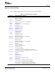
Table 18. MMC Command Register (MMCCMD) Field Descriptions (continued)
Bit Field Value Description
12 STRMTP Stream enable.
0 If WDATX = 1, the data transfer is a block transfer. The data transfer stops after the movement of the
programmed number of bytes (defined by the programmed block size and the programmed number of
blocks).
1 If WDATX = 1, the data transfer is a stream transfer. Once the data transfer is started, the data transfer
does not stop until the MMC controller issues a stop command to the memory card.
11 DTRW Write enable.
0 If WDATX = 1, the data transfer is a read operation.
1 If WDATX = 1, the data transfer is a write operation.
10-9 RSPFMT 0-3h Response format (expected type of response to the command).
0 No response.
1h R1, R4, R5, or R6 response. 48 bits with CRC.
2h R2 response. 136 bits with CRC.
3h R3 response. 48 bits with no CRC.
8 BSYEXP Busy expected. If an R1b (R1 with busy) response is expected, set RSPFMT = 1h and BSYEXP = 1.
0 A busy signal is not expected.
1 A busy signal is expected.
7 PPLEN Push pull enable.
0 Push pull driver of CMD line is disabled (open drain).
1 Push pull driver of CMD line is enabled.
6 Reserved 0 Reserved.
5-0 CMD 0-3Fh Command index. This field contains the command index for the command to be sent to the memory
card.
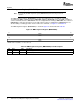
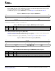
Figure 31. Command Format
47 46 45 40 39 24
Start Transmission Command index Argument, high part
23 8 7 1 0
Argument, low part CRC7 End
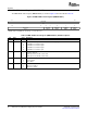
Table 19. Command Format
Bit Position of
Command Register Description
47 - Start bit
46 - Transmission bit
45-40 MMCCMD(5-0) Command index (CMD)
39-24 MMCARGHL Argument, high part (ARGH)
23-8 MMCARGHL Argument, low part (ARGL)
7-1 - CRC7
0 - End bit
SPRUE30B – September 2006 Multimedia Card (MMC)/Secure Digital (SD) Card Controller 53
Submit Documentation Feedback