
Computer Hardware User Manual
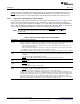

EM_CS[5:2]
EM_WE
EM_OE
EM_RW
EM_WAIT[5:2]
EM_BA[1:0]
EM_D[15:0]
EM_A[22:0]
EMIF
EM_D[7:0]
EM_A[21:0]
EM_BA[1:0]
DQ[7:0]
A[23:2]
A[1:0]
EMIF 8−bit
asynchronous
memory
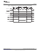
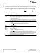
a) EMIF to 8-bit memory interface
EM_D[15:0]
EM_A[21:0]
EM_BA[1]
DQ[15:0]
A[22:1]
A[0]
EMIF 16−bit
asynchronous
memory
b) EMIF to 16-bit memory interface
www.ti.com
Architecture
2.5.1 Interfacing to Asynchronous Memory
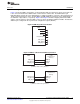
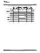
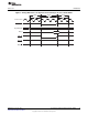
Figure 2 shows the EMIF's external pins used in interfacing with an asynchronous device. Of special note
is the connection between the EMIF and the external device's address bus. The EMIF address pin
EM_A[0] always provides the least significant bit of a 32-bit word address. Therefore, when interfacing to a
16-bit or 8-bit asynchronous device, the EM_BA[1] and EM_BA[0] pins provide the least-significant bits of
the halfword or byte address, respectively. Figure 2 and Figure 3 show the mapping between the EMIF
and the connected device's data and address pins for various programmed data bus widths. The data bus
width may be configured in the asynchronous configuration register (ACFGn).
Figure 2. EMIF Asynchronous Interface
Figure 3. EMIF to 8-bit and 16-bit Memory Interfaces
11
SPRUEQ7C–February 2010 Asynchronous External Memory Interface (EMIF)
Submit Documentation Feedback
Copyright © 2010, Texas Instruments Incorporated