
Computer Hardware User Manual

www.ti.com
Architecture
2.5.8 Extended Wait Mode and the EM_WAIT Pin
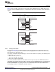
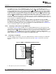
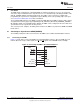
The Extended Wait mode is a mode in which the external asynchronous device may assert control over
the length of the strobe period. The Extended Wait mode can be entered by setting the EW bit in the
asynchronous configuration register (ACFGn). When the EW bit is set, the EMIF monitors the
EM_WAIT[5:2] pins to determine if the attached device wishes to extend the strobe period of the current
access cycle beyond the programmed number of clock cycles.
When the EMIF detects that the EM_WAIT pin has been asserted, it will begin inserting extra strobe
cycles into the operation until the EM_WAIT pin is deactivated by the external device. The EMIF will then
return to the last cycle of the programmed strobe period and the operation will proceed as usual from this
point. Refer to the device-specific data manual for details on the timing requirements of the EM_WAIT
signal.
The EM_WAIT pin cannot be used to extend the strobe period indefinitely. The programmable MEWC bit
in the asynchronous wait cycle configuration register (AWCCR) determines the maximum number of EMIF
clock cycles the strobe period may be extended beyond the programmed length. When the number of
cycles programmed in the MEWC bit expires, the EMIF proceeds to the hold period of the operation
regardless of the state of the EM_WAIT pin. The EMIF can also generate an interrupt upon expiration of
this counter. See Section 2.5.11.1 for details on enabling this interrupt.
For the EMIF to function properly in the Extended Wait mode, the WPn bit in AWCCR must be
programmed to match the polarity of the attached device. When the WPn bit is in its reset state of 1, the
EMIF will insert wait cycles when the EM_WAITn pin is sampled high; when the WPn bit is cleared to 0,
the EMIF will insert wait cycles only when the EM_WAITn pin is sampled low. This programmability allows
for a glueless connection to larger variety of asynchronous devices.
Finally, a restriction is placed on the setup and strobe period timing parameters when operating in
Extended Wait mode. Specifically, the sum of the W_SETUP and W_STROBE fields must be greater than
4, and the sum of the R_SETUP and R_STROBE fields must be greater than 4 for the EMIF to recognize
the EM_WAIT pin has been asserted. The W_SETUP, W_STROBE, R_SETUP, and R_STROBE fields
are in ACFGn.
2.5.9 Data Bus Parking
The EMIF always drives the data bus to the previous write data value when it is idle. This feature is called
data bus parking. Only when the EMIF issues a read command to the external memory does it stop
driving the data bus. After the EMIF latches the last read data, it immediately parks the data bus again.
2.5.10 Reset and Initialization Considerations
The EMIF and its registers will be reset when any of the following events occur:
1. The RESET pin on the device is asserted
2. The EMIF is placed in reset by the Power and Sleep Controller.
When a reset occurs, the EMIF will immediately abandon any access request that is in progress and reset
all registers and internal logic to their default state.
Following device power up and deassertion of the RESET pin, the internal clock to the EMIF is turned on
and the EMIF memory-mapped registers are programmed to their default values.
27
SPRUEQ7C–February 2010 Asynchronous External Memory Interface (EMIF)
Submit Documentation Feedback
Copyright © 2010, Texas Instruments Incorporated