
Computer Hardware User Manual

Architecture
www.ti.com
2.5.11 Interrupt Support
The EMIF has a single interrupt source (Table 13) mapped to the ARM interrupt controller. For more
information on the ARM interrupt controller (AINTC), see the TMS320DM646x DMSoC ARM Subsystem
Reference Guide (SPRUEP9).
Table 13. EMIF Interrupt
ARM Event Acronym Source
60 EMIFAINT EMIF
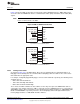
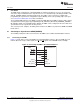
The EMIF supports a single interrupt to the CPU. Section 2.5.11.1 details the generation and internal
masking of EMIF interrupts and Section 2.5.11.2 describes how the EMIF interrupts are sent to the CPU.
2.5.11.1 Interrupt Events
There are two conditions that may cause the EMIF to generate an interrupt to the CPU. These two
conditions are:
• A rising edge on the EM_WAIT signal (wait rise interrupt)
• An asynchronous time out
The wait rise interrupt is not affected by the WPn bit in the asynchronous wait cycle configuration register
(AWCCR). The asynchronous time out interrupt condition occurs when the attached asynchronous device
fails to deassert the EM_WAIT pin within the number of cycles defined by the MEWC bit in AWCCR.
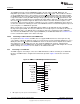
Only when the interrupt is enabled by setting the appropriate bit (WRMSETn or ATMSET) in the EMIF
interrupt mask set register (EIMSR) to 1, will the interrupt be sent to the CPU. Once enabled, the interrupt
may be disabled by writing a 1 to the corresponding bit in the EMIF interrupt mask clear register (EIMCR).
The bit fields in both the EIMSR and EIMCR may be used to indicate whether the interrupt is enabled.
When the interrupt is enabled, the corresponding bit field in both the EIMSR and EIMCR will have a value
of 1; when the interrupt is disabled, the corresponding bit field will have a value of 0.
The EMIF interrupt raw register (EIRR) and the EMIF interrupt mask register (EIMR) indicate the status of
each interrupt. The appropriate bit (WRn or AT) in EIRR is set when the interrupt condition occurs,
whether or not the interrupt has been enabled. Whereas, the appropriate bit (WRMn or ATM) in EIMR is
set only when the interrupt condition occurs and the interrupt is enabled. Writing a 1 to the bit in EIRR
clears the EIRR bit as well as the corresponding bit in EIMR.
Table 14 contains a brief summary of the interrupt status and control bit fields. See Section 4 for complete
details on the register fields.
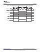
Table 14. Interrupt Monitor and Control Bit Fields
Register Name Bit Name Description
EMIF interrupt raw register WRn This bit is always set when an rising edge on the EM_WAIT signal occurs.
(EIRR) Writing a 1 clears the WRn bit as well as the WRMn bit in EIMR.
AT This bit is always set when an asynchronous timeout occurs. Writing a 1
clears the AT bit as well as the ATM bit in EIMR.
EMIF interrupt mask register WRMn This bit is only set when a rising edge on the EM_WAIT signal occurs and
(EIMR) the interrupt has been enabled by writing a 1 to the WRMSETn bit in
EIMSR.
ATM This bit is only set when an asynchronous timeout occurs and the interrupt
has been enabled by writing a 1 to the ATMSET bit in EIMSR.
EMIF interrupt mask set register WRMSETn Writing a 1 to this bit enables the wait rise interrupt.
(EIMSR)
ATMSET Writing a 1 to this bit enables the asynchronous timeout interrupt.
EMIF interrupt mask clear register WRMCLRn Writing a 1 to this bit disables the wait rise interrupt.
(EIMCR)
ATMCLR Writing a 1 to this bit disables the asynchronous timeout interrupt.
28
Asynchronous External Memory Interface (EMIF) SPRUEQ7C–February 2010
Submit Documentation Feedback
Copyright © 2010, Texas Instruments Incorporated