
Computer Hardware User Manual

Registers
www.ti.com
4.2 Asynchronous Wait Cycle Configuration Register (AWCCR)
The asynchronous wait cycle configuration register (AWCCR) is used to configure the parameters for
extended wait cycles. Both the polarity of the EM_WAIT[5:2] pins and the maximum allowable number of
extended wait cycles can be configured. the AWCCR is shown in Figure 21 and described in Table 34.
NOTE: The EW bit in the asynchronous configuration register (ACFGn) must be set to allow for the
insertion of extended wait cycles.
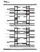
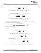
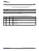
Figure 21. Asynchronous Wait Cycle Configuration Register (AWCCR)
31 30 29 28 27 24 23 22 21 20 19 18 17 16
WP3 WP2 WP1 WP0 Reserved CS5_WAIT CS4_WAIT CS3_WAIT CS2_WAIT
R/W-1 R/W-1 R/W-1 R/W-1 R-0 R/W-3h R/W-2h R/W-1 R/W-0
15 8 7 0
Reserved MEWC
R-0 R/W-80h
LEGEND: R/W = Read/Write; R = Read only; -n = value after reset
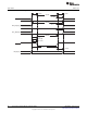
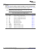
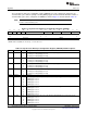
Table 34. Asynchronous Wait Cycle Configuration Register (AWCCR) Field Descriptions
Bit Field Value Description
31 WP3 WAIT polarity bit. This bit defines the polarity of the EM_WAIT[5] pin.
0 Insert wait cycles if EM_WAIT[5] pin is low.
1 Insert wait cycles if EM_WAIT[5] pin is high.
30 WP2 WAIT polarity bit. This bit defines the polarity of the EM_WAIT[4] pin.
0 Insert wait cycles if EM_WAIT[4] pin is low.
1 Insert wait cycles if EM_WAIT[4] pin is high.
29 WP1 WAIT polarity bit. This bit defines the polarity of the EM_WAIT[3] pin.
0 Insert wait cycles if EM_WAIT[3] pin is low.
1 Insert wait cycles if EM_WAIT[3] pin is high.
28 WP0 WAIT polarity bit. This bit defines the polarity of the EM_WAIT[2] pin.
0 Insert wait cycles if EM_WAIT[2] pin is low.
1 Insert wait cycles if EM_WAIT[2] pin is high.
27-24 Reserved 0 Reserved
23-22 CS5_WAIT 0-3h EM_WAIT[5:2] pin map for chip select 5. By default, the EM_WAIT[5] pin is used for chip select 5.
0 EM_WAIT[2] pin is used.
1h EM_WAIT[3] pin is used.
2h EM_WAIT[4] pin is used.
3h EM_WAIT[5] pin is used.
21-20 CS4_WAIT 0-3h EM_WAIT[5:2] pin map for chip select 4. By default, the EM_WAIT[4] pin is used for chip select 4.
0 EM_WAIT[2] pin is used.
1h EM_WAIT[3] pin is used.
2h EM_WAIT[4] pin is used.
3h EM_WAIT[5] pin is used.
19-18 CS3_WAIT 0-3h EM_WAIT[5:2] pin map for chip select 3. By default, the EM_WAIT[3] pin is used for chip select 3.
0 EM_WAIT[2] pin is used.
1h EM_WAIT[3] pin is used.
2h EM_WAIT[4] pin is used.
3h EM_WAIT[5] pin is used.
50
Asynchronous External Memory Interface (EMIF) SPRUEQ7C–February 2010
Submit Documentation Feedback
Copyright © 2010, Texas Instruments Incorporated