
Video Port/VCXO Interpolated Control (VIC) Port User's Guide


www.ti.com
525
2
1
4
3
6
5
19
Field1active
Field1image
20
21
22
23
262
263
264
265
266
267
268
269
282
Field2active
283
284
285
286
Field2image
524
525
1
Field1blanking
1
2
1
2
239
240
240
240
240
240
240
240
240
240
240
240
240
240
240
239
240
240
240
240
240
240
240
240
240
240
240
240
ILCOUNTFLCOUNT
0 1
11
1 1
1 1
1 0
1 0
1 0
01
00
0 0
0
0
0
0
0 0
00
0 0
0 0
1 0
1 0
1 1
1 1
1 1
1 1
1 1
0 1
0 1
0 1
0 1
0 1
0 0
0 1
1 1
1 1
EAV
V F
FLD
VBLNK
AB
VSYNC
AB
Active
horizontal
output
FIFOdata
FIFOdata
Blankingvalue
Blankingvalue
Blankingvalue
Blankingvalue
Blankingvalue
Blankingvalue
Blankingvalue
Blankingvalue
Defaultvalue§
Defaultvalue§
Defaultvalue§
FIFOdata
FIFOdata
Defaultvalue§
Blankingvalue
Blankingvalue
Blankingvalue
Blankingvalue
Blankingvalue
Blankingvalue
Blankingvalue
Defaultvalue§
Defaultvalue§
Defaultvalue§
FIFOdata
FIFOdata
FIFOdata
FIFOdata
Blankingvalue
Blankingvalue
IMGVOFF1=3
IMGVSIZE1=240
IMGVOFF2=3
IMGVSIZE2=240
FRMHEIGHT =525
VBITSET1=1
VBITCLR1=20
VBITSET2=264
VBITCLR2=283
VBLNKXSTART1=720
VBLNKYSTART1=1
VBLNKXSTOP1-720
VBLNKYSTOP1-20
VBLNKXSTAR2=360
VBLNKYSTART2=263
VBLNKXSTOP2=360
BLNKYSTOP2=283
VSYNCXSTART1=720
VSYNCYSTART1=4
VSYNCXSTOP1=720
VSYNCYSTOP1=7
VSYNCXSTART2=360
VSYNCYSTART2=266
VSYNCXSTOP2=360
VSYNCYSTOP2=269
FLD1XSTART =720
FLD1YSTART =1
FLD2XSTART =360
FLD2YSTART =263
FBITSET =266
FBITCLR=4
Field2blanking
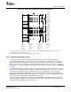
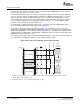
4.9.2 Interlaced Raw Display Example
Display Timing Examples
Figure 4-26. BT.656 Interlaced Display Vertical Timing Example
A Assumes VCT1P bit in VPCTL is set to 1 (active-low output). VSYNC output when VCTL2S bit in VDCTL is set to 00,
VBLNK output when VCTL2S bit is set 01.
B If DVEN bit in VDCTL is set to 1; otherwise, blanking value is output.
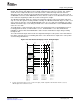
This section shows an example of raw display output for the same 704 x 408 interlaced image.
The horizontal output timing is shown in Figure 4-27 . This diagram assumes that there is a two VCLK
pipeline delay between the internal counter changing and the output on external pins. The actual delay
can be longer or shorter as long as it is consistent within any display mode. The active line is 720-pixels
wide. Figure 4-27 shows the 704-pixel image window centered in the screen that results in an IMGHOFF x
of 8 pixels.
The HBLNK and HSYNC signals are shown as they would be output for active-low operation. Note that
only one of the two signals is actually available externally. The HBLNK inactive edge occurs on sample 0.
The IPCOUNT operation follows the description in Section 4.1.2 . IPCOUNT resets to 0 at the first
displayed pixel (FPCOUNT = IMGHOFF x) and stops counting at the last displayed pixel (IPCOUNT =
IMGHSIZE x). Both the IPCOUNT and FPCOUNT counters increment on every third VCLKIN rising edge,
as programmed by the INCPIX bits in VDTHRLD with a value of 3.
VDOUT shows the output data and switching between Default Data, and FIFO Data. Three values are
output sequentially on VDOUT for each pixel count. Note that the default value is output during both the
blanking and non-display image active video regions.
SPRUEM1 – May 2007 Video Display Port 113
Submit Documentation Feedback