
Video Port/VCXO Interpolated Control (VIC) Port User's Guide


www.ti.com
525
2
1
4
3
6
5
19
Field1active
Field1image
20
21
22
23
262
263
264
265
266
267
268
269
282
Field2active
283
284
285
286
Field2image
524
525
1
Field1blanking
1
2
1
2
239
240
240
240
240
240
240
240
240
240
240
240
240
240
240
239
240
240
240
240
240
240
240
240
240
240
240
240
ILCOUNTFLCOUNT
FLD
VBLNK
A
VSYNC
A
Active
horizontal
output
FIFOdata
FIFOdata
Defaultvalue
Defaultvalue
FIFOdata
FIFOdata
FIFOdata
FIFOdata
FIFOdata
FIFOdata
IMGVOFF1=2
IMGVSIZE1=240
IMGVOFF2=3
IMGVSIZE2=240
FRMHEIGHT =525
VBITSET1=n/a
VBITCLR1=n/a
VBITSET2=n/a
VBITCLR2=n/a
VBLNKXSTART1=720
VBLNKYSTART1=1
VBLNKXSTOP1-720
VBLNKYSTOP1-21
VBLNKXSTAR2=360
VBLNKYSTART2=263
VBLNKXSTOP2=360
BLNKYSTOP2=283
VSYNCXSTART1=720
VSYNCYSTART1=4
VSYNCXSTOP1=720
VSYNCYSTOP1=7
VSYNCXSTART2=360
VSYNCYSTART2=266
VSYNCXSTOP2=360
VSYNCYSTOP2=269
FLD1XSTART =720
FLD1YSTART =1
FLD2XSTART =360
FLD2YSTART =263
FBITSET =n/a
FBITCLR=n/a
Defaultvalue
Defaultvalue
Defaultvalue
Defaultvalue
Defaultvalue
Defaultvalue
Defaultvalue
Defaultvalue
Defaultvalue
Defaultvalue
Defaultvalue
Defaultvalue
Defaultvalue
Defaultvalue
Defaultvalue
Defaultvalue
Defaultvalue
Defaultvalue
Defaultvalue
Defaultvalue
Defaultvalue
Defaultvalue
Field2blanking
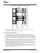
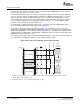
Display Timing Examples
The vertical output timing for raw mode is shown in Figure 4-28 . This example outputs the same 480-line
window. Note that the raw display mode is typically noninterlaced for output to a monitor. This example
shows the more complex interlaced case. The active field 1 is 242.5-lines high and active field 2 is
242.5-lines high. This example shows the 480-line image window centered in the screen. This results in
an IMGVOFF1 of 2 lines and an IMGVOFF2 of 3 lines and also results in a non-data half-line at the end of
field 1 and at the beginning of field 2 due to their non-integer line lengths.
The VBLNK and VSYNC signals are shown as they would be output for active-low operation. Note that
only one of the two signals is actually available externally. The VBLNK and VSYNC edges for field 1 occur
at the end of an active line so their XSTART/XSTOP values are set to 720 (start of blanking). For field 2,
VBLNK and VSYNC edges occur during the middle of the active horizontal line so their XSTART/XSTOP
values are set to 360.
The FLD output is setup to transition at the start of each analog field (start of vertical blanking). There is
no EAV[F] bit in raw mode, so FLD1YSTRT is set to 1, FLD2YSTART is set to 263, FBITCLR and
FBITSET are ignored. Note that FLD2XSTRT is 360 so that the field indicator output changes halfway
through the line.
The active horizontal output column shows the output data during the active portion of the horizontal line.
Note that in raw mode there is no blanking data value so the default value is output for the active portion
of all non-image window lines.
Figure 4-28. Raw Interlaced Display Vertical Timing Example
A Assumes VCT1P bit in VPCTL is set to 1 (active-low output). VSYNC output when VCTL2S bit in VDCTL is set to 00,
VBLNK output when VCTL2S bit is set 01.
SPRUEM1 – May 2007 Video Display Port 115
Submit Documentation Feedback