
Video Port/VCXO Interpolated Control (VIC) Port User's Guide

www.ti.com
4.12.12 Video Display Field 2 Image Size Register (VDIMGSZ2)
4.12.13 Video Display Field 1 Timing Register (VDFLDT1)
Video Display Registers
The video display field 2 image size register (VDIMGSZ2) defines the field 2 image area and specifies the
size of the displayed image within the active display.
The image pixel counter (IPCOUNT) counts displayed image pixel output on each of the displayed image.
Displayed image pixel output stops when IPCOUNT = IMGHSIZE2. The default output values or blanking
values are output for the remainder of the active line.
The image line counter (ILCOUNT) counts displayed image lines. Displayed image output stops when
ILCOUNT = IMGVSIZE2. The default output values or blanking values are output for the remainder of the
active field.
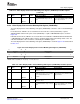
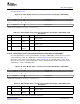
The video display field 2 image size register (VDIMGSZ2) is shown in Figure 4-42 and described in
Table 4-17
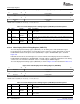
Figure 4-42. Video Display Field 2 Image Size Register (VDIMGSZ2)
31 28 27 16
Reserved IMGVSIZE2
R-0 R/W-0
15 12 11 0
Reserved IMGHSIZE2
R-0 R/W-0
LEGEND: R/W = Read/Write; R = Read only; - n = value after reset
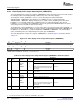
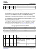
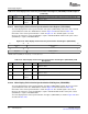
Table 4-17. Video Display Field 2 Image Size Register (VDIMGSZ2) Field Descriptions
Description
Bit field
(1)
symval
(1)
Value BT.656 and Y/C Mode Raw Data Mode
31-28 Reserved - 0 Reserved. The reserved bit location is always read as 0. A value written to this field
has no effect.
27-16 IMGVSIZE2 OF( value) 0-FFFh Specifies the display image height in lines.
DEFAULT 0
15-12 Reserved - 0 Reserved. The reserved bit location is always read as 0. A value written to this field
has no effect.
11-0 IMGHSIZE2 OF( value) 0-FFFh Specifies the display image width in Specifies the display image width in
pixels. This number must be even (the pixels.
LSB is treated as 0).
DEFAULT 0
(1)
For CSL implementation, use the notation VP_VDIMGSZ2_ field_ symval
In raw data mode, the FLD signal is de-asserted to indicate field 1 display whenever the frame line
counter (FLCOUNT) is equal to FLD1YSTART and the frame pixel counter (FPCOUNT) is equal to
FLD1XSTART (this is shown in Figure 4-6 .
In BT.656 and Y/C mode, the FLD signal is de-asserted to indicate field 1 display whenever FLCOUNT =
FLD1YSTART and FPCOUNT = FLD1XSTART. The FLD output is completely independent of the timing
control codes. The F bit in the EAV/SAV codes is controlled by the VDFBIT register.
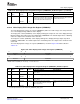
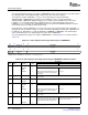
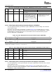
The video display field 1 timing register (VDFLDT1) sets the timing of the field identification signal. The
VDFLDT1 is shown in Figure 4-43 and described in Table 4-18 .
SPRUEM1 – May 2007 Video Display Port 135
Submit Documentation Feedback