
Video Port/VCXO Interpolated Control (VIC) Port User's Guide

www.ti.com
4.12.15 Video Display Threshold Register (VDTHRLD)
Video Display Registers
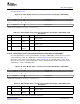
Table 4-19. Video Display Field 2 Timing Register (VDFLDT2) Field Descriptions (continued)
Bit field
(1)
symval
(1)
Value Description
11-0 FLD2XSTART OF( value) 0-FFFh Specifies the pixel on the first line of field 2 where the FLD output is asserted.
DEFAULT 0
The video display threshold register (VDTHRLD) sets the display FIFO threshold to determine when to
load more display data.
The VDTHRLD n bits determines how much space must be available in the display FIFOs before the
appropriate EDMA event may be generated. The Y FIFO uses the VDTHRLD n value directly while the Cb
and Cr values use ½ the VDTHRLD n value rounded up to the next double word (½ (VDTHRLD n +
VTHRLD n mod 2). The EDMA transfer size must be less than the value used for each FIFO. Typically,
VDTHRLD n is set to the horizontal line length rounded up to the next double word boundary. For non-line
length thresholds, the display data unpacking mechanism places certain restrictions of what VDTHRLD n
values are valid (see Section 2.3.3 ).
The VDTHRLD2 bits behaves identically to VDTHRLD1, but are used during field 2 capture. It is used only
if the field 2 EDMA size needs to be different from the field 1 EDMA size for some reason (for example,
different display line lengths in field 1 and field 2).
In raw display mode, the INCPIX bits determine when the frame pixel counter (FPCOUNT) is incremented
. If, for example, each output value represents the R, G, or B portion of a display pixel, then the INCPIX
bits are set to 3h so that the pixel counter is incremented only on every third output clock. An INCPIX
value of 0h represents a count of 16 rather than 0.
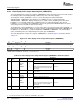
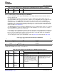
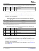
The video display threshold register (VDTHRLD) is shown in Figure 4-45 and described in Table 4-20 .
Figure 4-45. Video Display Threshold Register (VDTHRLD)
31 26 25 16
Reserved VDTHRLD2
R-0 R/W-0
15 12 11 10 9 0
INCPIX Reserved VDTHRLD1
R/W-0001 R-0 R/W-0
LEGEND: R/W = Read/Write; R = Read only; - n = value after reset
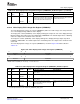
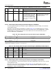
Table 4-20. Video Display Threshold Register (VDTHRLD) Field Descriptions
Description
Bit field
(1)
symval
(1)
Value BT.656 and Y/C Mode Raw Data Mode
31-26 Reserved - 0 Reserved. The reserved bit location is always read as 0. A value written to this field
has no effect.
25-16 VDTHRLD2 OF( value) 0-3FFh Field 2 threshold. Whenever there are at Field 2 threshold. Whenever there are at
least VDTHRLD double words of space least VDTHRLD double words of space
in the Y display FIFO, a new Y EDMA in the display FIFO, a new Y EDMA
event may be generated. Whenever event may be generated.
there are at least ½ VDTHRLD double
words of space in the Cb or Cr display
FIFO, a new Cb or Cr EDMA event may
be generated.
DEFAULT 0
15-12 INCPIX OF( value) 0-Fh Not used. FPCOUNT is incremented every INCPIX
output clocks.
DEFAULT 1
(1)
For CSL implementation, use the notation VP_VDTHRLD_ field_ symval
SPRUEM1 – May 2007 Video Display Port 137
Submit Documentation Feedback