
Video Port/VCXO Interpolated Control (VIC) Port User's Guide

www.ti.com
4.12.18 Video Display Field 1 Vertical Synchronization End Register (VDVSYNE1)
Video Display Registers
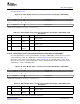
The video display field 1 vertical synchronization start register (VDVSYNS1) is shown in Figure 4-47 and
described in Table 4-22 .
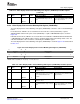
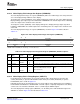
Figure 4-47. Video Display Field 1 Vertical Synchronization Start Register (VDVSYNS1)
31 28 27 16
Reserved VSYNCYSTART1
R-0 R/W-0
15 12 11 0
Reserved VSYNCXSTART1
R-0 R/W-0
LEGEND: R/W = Read/Write; R = Read only; - n = value after reset
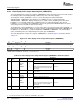
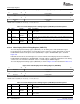
Table 4-22. Video Display Field 1 Vertical Synchronization Start Register (VDVSYNS1) Field
Descriptions
Bit field
(1)
symval
(1)
Value Description
31-28 Reserved - 0 Reserved. The reserved bit location is always read as 0. A value written to this
field has no effect.
27-16 VSYNCYSTART1 OF( value) 0-FFFh Specifies the line where VSYNC is asserted for field 1.
DEFAULT 0
15-12 Reserved - 0 Reserved. The reserved bit location is always read as 0. A value written to this
field has no effect.
11-0 VSYNCXSTART1 OF( value) 0-FFFh Specifies the pixel where VSYNC is asserted in field 1.
DEFAULT 0
(1)
For CSL implementation, use the notation VP_VDVSYNS1_ field_ symval
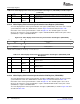
The video display field 1 vertical synchronization end register (VDVSYNE1) controls the end of vertical
synchronization in field 1. The VDVSYNE1 is shown in Figure 4-48 and described in Table 4-23 .
Generation of the vertical synchronization is shown in Figure 4-6 . The VSYNC signal is de-asserted
whenever the frame line counter (FLCOUNT) is equal to VSYNCYSTOP1 and the frame pixel counter
(FPCOUNT) is equal to VSYNCXSTOP1.
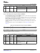
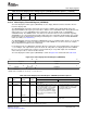
Figure 4-48. Video Display Field 1 Vertical Synchronization End Register (VDVSYNE1)
31 28 27 16
Reserved VSYNCYSTOP1
R-0 R/W-0
15 12 11 0
Reserved VSYNCXSTOP1
R-0 R/W-0
LEGEND: R/W = Read/Write; R = Read only; - n = value after reset
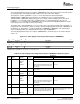
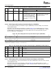
Table 4-23. Video Display Field 1 Vertical Synchronization End Register (VDVSYNE1) Field
Descriptions
Bit field
(1)
symval
(1)
Value Description
31-28 Reserved - 0 Reserved. The reserved bit location is always read as 0. A value written to this
field has no effect.
27-16 VSYNCYSTOP1 OF( value) 0-FFFh Specifies the line where VSYNC is de-asserted for field 1.
DEFAULT 0
(1)
For CSL implementation, use the notation VP_VDVSYNE1_ field_ symval
SPRUEM1 – May 2007 Video Display Port 139
Submit Documentation Feedback