
Video Port/VCXO Interpolated Control (VIC) Port User's Guide

www.ti.com
4.12.27 Video Display Field 1 Vertical Blanking Bit Register (VDVBIT1)
Video Display Registers
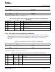
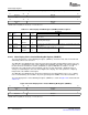
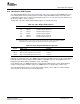
Figure 4-57. Video Display Field Bit Register (VDFBIT)
31 28 27 16
Reserved FBITSET
R-0 R/W-0
15 12 11 0
Reserved FBITCLR
R-0 R/W-0
LEGEND: R/W = Read/Write; R = Read only; - n = value after reset
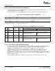
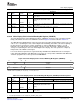
Table 4-31. Video Display Field Bit Register (VDFBIT) Field Descriptions
Description
Bit field
(1)
symval
(1)
Value BT.656 and Y/C Mode Raw Data Mode
31-28 Reserved - 0 Reserved. The reserved bit location is always read as 0. A value written to this field
has no effect.
27-16 FBITSET OF( value) 0-FFFh Specifies the first line with an EAV of F = Not used.
1 indicating field 2 display.
DEFAULT 0
15-12 Reserved - 0 Reserved. The reserved bit location is always read as 0. A value written to this field
has no effect.
11-0 FBITCLR OF( value) 0-FFFh Specifies the first line with an EAV of F = Not used.
0 indicating field 1 display.
DEFAULT 0
(1)
For CSL implementation, use the notation VP_VDFBIT_ field_ symval
The video display field 1 vertical blanking bit register (VDVBIT1) controls the V bit value in the EAV and
SAV timing control codes for field 1.
The VBITSET1 and VBITCLR1 bits control the V bit value in the EAV and SAV timing control codes. The
V bit is set to 1 (indicating the start of field 1 digital vertical blanking) in the EAV code at the beginning of
the line whenever the frame line counter (FLCOUNT) is equal to VBITSET1. It remains a 1 for all
EAV/SAV codes until the EAV at the beginning of the line on when FLCOUNT = VBITCLR1 where it
changes to 0 (indicating the start of the field 1 digital active display). The V bit operation is completely
independent of the VBLNK control signal.
The VBITSET1 and VBITCLR1 bits should be programmed so that FLCOUNT becomes set to 1 during
field 1 vertical blanking. The hardware only starts generating field 1 EDMA events when FLCOUNT = 1.
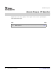
The video display field 1 vertical blanking bit register (VDVBIT1) is shown in Figure 4-58 and described in
Table 4-32 .
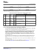
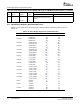
Figure 4-58. Video Display Field 1 Vertical Blanking Bit Register (VDVBIT1)
31 28 27 16
Reserved VBITCLR1
R-0 R/W-0
15 12 11 0
Reserved VBITSET1
R-0 R/W-0
LEGEND: R/W = Read/Write; R = Read only; - n = value after reset
Video Display Port146 SPRUEM1 – May 2007
Submit Documentation Feedback