
Video Port/VCXO Interpolated Control (VIC) Port User's Guide

www.ti.com
6.3 Operational Details
R + kf
k u (
3
Ǹ
(p
2
(2
b
* 1)
2
)ń3)
Operational Details
Synchronization is an important aspect of decoding and presenting data in real-time digital data delivery
systems. This is addressed in the MPEG transport packets by transmitting timing information in the
adaptation fields of selected data packets. This serves as a reference for timing comparison in the
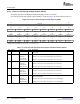
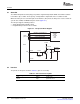
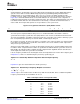
receiving system. A sample of the 27-MHz clock, the program clock reference (PCR) header is shown in
Figure 6-2 , is transmitted within the bit stream, which indicates the expected time at the completion of
reading the field from the bit stream at the transport decoder. The sample is a 42-bit field, 9 bits cycle from
0 to 299 at 27 MHz, while the other 33-bit field is incremented by 1 each time the 9-bit field reaches a
value of 299. The transport data packets are in sync with the server system clock.
Figure 6-2. Program Clock Reference (PCR) Header Format
47 15 14 9 8 0
PCR Reserved PCR extension
The video port in conjunction with the VIC port uses a combined hardware and software solution to
synchronize the transport system time clock (STC) with the clock reference transmitted in the bit stream.
The video port maintains a hardware counter that counts the system time. The counter is driven by system
time clock (STCLK) input driven by an external VCXO, controlled by the VIC port.
On reception of a packet, the video port captures a snapshot of the counter. Software uses this timestamp
to determine the deviation of the system time clock from the server clock, and drives VCTL output of the
VIC port to keep it synchronized.
Any time a packet with a PCR is received, the timestamp for that packet is compared with the PCR value
in software. A PLL is implemented in software to synchronize the STCLK with the system time clock. The
DSP updates the VIC input register (VICIN) using the output from this algorithm, which in turn drives the
VCTL output that controls the system time clock VCXO.
If fis the frequency of PCRs in the incoming bit stream, the interpolation rate R of the VCTL output is given
in Equation 6-1 , where k is determined by the precision β specified by you.
Equation 6-1. Relationship Between Interpolation Rate and Input Frequency
Equation 6-2 gives the relation between k and the precision β .
Equation 6-2. Relationship of Frequency Multiplier to Precision
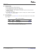
Table 6-2 gives some k and R values for different β 's with f fixed at 40 kHz. Once a suitable interpolation
frequency is determined, the clock divider can be set.
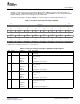
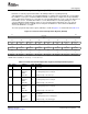
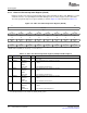
Table 6-2. Example Values for Interpolation Rate
β k R
9 96.0 3.8 MHz
10 151.0 6.0 MHz
11 240.0 9.6 MHz
12 381.0 15.2 MHz
13 605.0 24.2 MHz
14 960.0 38.4 MHz
15 1523.0 60.9 MHz
16 2418.0 96.7 MHz
SPRUEM1 – May 2007 VCXO Interpolated Control Port 169
Submit Documentation Feedback