
Video Port/VCXO Interpolated Control (VIC) Port User's Guide


www.ti.com
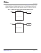
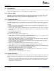
VDIN[19−12]
8
Buffer B (2560 bytes)
Capture FIFO B
YSRCB
64
VDIN[9−2]
8
Buffer A (2560 bytes)
Capture FIFO A
YSRCA
64
Video Port FIFO
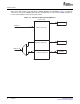
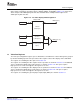
For 8-bit raw video, the FIFO is split into channel A and B, as shown in Figure 1-3 . Each FIFO is clocked
independently with the channel A FIFO receiving data from the VDIN[9-2] half of the bus and the channel
B FIFO receiving data from the VDIN[19-12] half of the bus. Each channel's FIFO has a separate write
pointer and read register (YSRC x). The FIFO configuration is identical for TCI capture, but channel B is
disabled.
Figure 1-3. 8-Bit Raw Video Capture and TCI Video Capture FIFO Configuration
SPRUEM1 – May 2007 Overview 21
Submit Documentation Feedback