
Video Port/VCXO Interpolated Control (VIC) Port User's Guide


www.ti.com
Buffer A (2560 bytes)
YDSTA
VDOUT[9−2]
64
8
Display FIFO A
Buffer B (2560 bytes)
YDSTB
VDOUT[19−12]
64
8
Display FIFO B
Data Buffer (5120 bytes)
YDSTA
VDOUT[19−2]
64
16
Display FIFO
Video Port FIFO
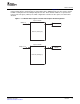
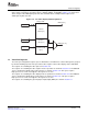
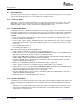
For locked raw video, the FIFO is split into channel A and B. The channels are locked together and use
the same clock and control signals. Each channel uses a single buffer and write register (YDST x) as
shown in Figure 1-8 .
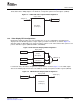
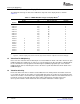
For 16-bit raw video, the FIFO is configured as a single buffer, as shown in Figure 1-9 . The FIFO outputs
data on VDOUT[19-2]. The FIFO has a single read pointer and write register (YDSTA).
Figure 1-8. 8-Bit Locked Raw Video Display FIFO Configuration
Figure 1-9. 16-Bit Raw Video Display FIFO Configuration
24 Overview SPRUEM1 – May 2007
Submit Documentation Feedback