
Video Port/VCXO Interpolated Control (VIC) Port User's Guide

www.ti.com
Video Port Control Registers
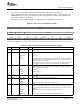
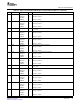
Table 2-2. Video Port Control Register (VPCTL) Field Descriptions (continued)
Bit field
(1)
symval
(1)
Value Description
5 VCT2P OF( value) VCTL2 pin polarity bit. Does not affect GPIO operation.
DEFAULT 0 Indicates the VCTL2 control signal (input or output) is active high.
NONE
ACTIVELOW 1 Indicates the VCTL2 control signal (input or output) is active low.
4 VCT1P OF( value) VCTL1 pin polarity bit. Does not affect GPIO operation.
ACTIVEHIGH 0 Indicates the VCTL1 control signal (input or output) is active high.
NONE
ACTIVELOW 1 Indicates the VCTL1 control signal (input or output) is active low.
3 Reserved - 0 Reserved. The reserved bit location is always read as 0. A value written to this field
has no effect.
2 TCI OF( value) TCI capture mode select bit.
DEFAULT 0 TCI capture mode is disabled.
NONE
CAPTURE 1 TCI capture mode is enabled.
1 DISP OF( value) Display mode select bit. VDATA pins are configured for output. VCLK2 pin is
configured as VCLKOUT output.
DEFAULT 0 Capture mode is enabled.
CAPTURE
DISPLAY 1 Display mode is enabled.
0 DCHNL OF( value) Dual channel operation select bit. If the DCDIS bit in VPSTAT is set, this bit is forced
to 0.
DEFAULT 0 Single-channel operation is enabled.
SINGLE
DUAL 1 Dual-channel operation is enabled.
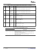
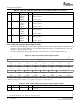
Table 2-3. Video Port Operating Mode Selection
VPCTL Bit
TCI DISP DCHNL Operating Mode
0 0 0 Single channel video capture. BT.656, Y/C or raw mode as selected in VCACTL. Video
capture B channel not used.
0 0 1 Dual channel video capture. Either BT.656 or raw 8-bit as selected in VCACTL and
VCBCTL. Option is available only if DCDIS is 0.
0 1 x Single channel video display. BT.656, Y/C or raw mode as selected in VDCTL. Video
display B channel is only used for dual channel sync raw mode.
1 x x Single channel TCI capture.
Video Port36 SPRUEM1 – May 2007
Submit Documentation Feedback