
Video Port/VCXO Interpolated Control (VIC) Port User's Guide

www.ti.com
3.1 Video Capture Mode Selection
3.2 BT.656 Video Capture Mode
3.2.1 BT.656 Capture Channels
3.2.2 BT.656 Timing Reference Codes
Video Capture Mode Selection
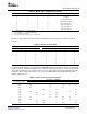
The video capture module operates in one of five modes as listed in Table 3-1 . The transport channel
interface (TCI) selection is made using the TCI bit in the video port control register (VPCTL). The CMODE
bits are in the video capture channel x control register (VC xCTL). The Y/C and 16-bit raw capture modes
may only be selected for channel A and only if the DCDIS bit in VPCTL is cleared to 0.
When operating as a raw video capture channel, no data selection or data interpretation is performed. The
16-bit raw capture mode is designed to accept data from A/D converters with resolution higher than eight
bits (used, for example, in medical imaging).
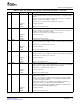
Table 3-1. Video Capture Mode Selection
TCI Bit CMODE Bits Mode Description
0 000 8-Bit ITU-R BT.656 Capture Digital video input is in YCbCr 4:2:2 with 8-bit resolution
multiplexed in ITU-R BT.656 format.
0 010 8-Bit Raw Capture Raw 8-bit data capture at sampling rates up to 80 MHZ.
0 100 8-Bit Y/C Capture Digital video input is in YCbCr 4:2:2 with 8-bit resolution on
parallel Y and Cb/Cr multiplexed channels.
0 110 16-Bit Raw Capture Raw 16-bit data capture at sampling rates up to 80 MHZ.
1 010 TCI Capture 8-bit parallel TCI capture at rates up to 30 MHZ.
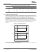
The BT.656 capture mode captures 8-bit 4:2:2 luma and chroma data multiplexed into a single data
stream. Video data is conveyed in the order Cb, Y, Cr, Y, Cb, Y, Cr, etc. where the sequence Cb, Y, Cr
refers to co-sited luma and chroma samples and the following Y value corresponds to the next luminance
sample. The data stream is de-multiplexed and each component is written in packed form into separate
FIFOs for transfer into Y, Cb, and Cr buffers in DSP memory. (This is commonly called planar format).
In BT.656 video capture mode, data bytes in which the 8 bits are all set to 1 (FFh) or are all set to 0 (00h)
are reserved for data identification purposes and consequently, only 254 of the possible 256 8-bit words
may be used to express signal value.
In dual channel operation, the video port can support capture of two BT.656 data streams or one BT.656
data stream and one raw data stream. In the latter case, the BT.656 stream may occur on either Channel
A or Channel B. In either case, the BT.656 stream(s) must have embedded timing reference codes and
the appropriate VCTL input must be used as a CAPEN signal.
If the port is configured for single channel operation, capture will take place on Channel A only. The
unused half of the VDATA bus may be used for GPIO or for another peripheral function. For single
channel operation, non-standard BT.656 data streams without embedded timing reference codes are
supported through the use of the timing control (VCTL) input signals.
For standard digital video, there are two reference signals, one at the beginning of each video data block
(start of active video, SAV), and one at the end of each video block (end of active video, EAV).
(Technically each line begins with the EAV code and ends just before the subsequent EAV code.) Each
timing reference signal consists of a four sample sequence in the following format: FFh, 00h, 00h, XYh.
(The FFh and 00h values are reserved for use in these timing reference signals.) The first three bytes are
a fixed preamble. The fourth byte contains information defining field identification, the state of field
blanking and state of line blanking. The assignment of these bits within the timing reference signal is listed
in Table 3-2 .
46 Video Capture Port SPRUEM1 – May 2007
Submit Documentation Feedback