
Video Port/VCXO Interpolated Control (VIC) Port User's Guide

www.ti.com
3.2.4 BT.656 Data Sampling
3.2.5 BT.656 FIFO Packing
BT.656 Video Capture Mode
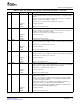
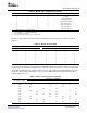
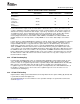
Table 3-5. Common Video Source Parameters
Number of Active Lines
Video Source (Field 1/Field 2) Number of Active Pixels Field Rate (Hz)
square pixel 240/240 640 60
60 Hz/525 lines
BT.601 244/243 720 60
60 Hz/525 lines
square pixel 288/288 768 50
50Hz/625 lines
BT.601 288/288 720 50
50 Hz/625 lines
For the BT.656 video capture mode, the FIFO buffer is divided into three sections (three buffers). One
section is 1280 bytes deep and is dedicated for storage of Y data samples. The other two sections are
dedicated for storage of Cb and Cr data samples, respectively. The buffers for Cb and Cr samples are
each 640 bytes deep. The incoming video data stream is separated into Y, Cb, and Cr data streams,
scaled (if selected), and the Y, Cb, and Cr buffers are filled. Each of the three buffers has a
memory-mapped location associated with it; YSRC, CBSRC, and CRSRC. The YSRC, CBSRC, and
CRSRC locations are read only and are used by EDMAs to access video data samples stored in the
FIFOs.
If video capture is enabled (BLKCAP bit in VC xCTL is cleared), pixels in the capture window are captured
in the Y, Cb, and Cr buffers. The video capture module uses the YEVT, CbEVT, and CrEVT events to
notify the EDMA controller to copy data from the capture buffers to the DSP memory. The number of
double words required to generate the events is set by the VCTHRLD n bits in VC xTHRLD. On every
YEVT, the EDMA should move data from the Y buffer to DSP memory using the YSRC location as the
source address. On every CbEVT, the EDMA should move data from the Cb buffer to DSP memory using
the CBSRC location as the source address. On every CrEVT, the EDMA should move data from the Cr
buffer to DSP memory using the CRSRC location as the source address. Note that transfer size from the
Cb and Cr buffers is half of the transfer size from the Y buffer since for every four Y samples, there are
two Cb and two Cr samples.
Incoming data (including timing codes) are sampled and the HCOUNT counter advanced only on clock
cycles for which the CAPEN input is active. Inputs when CAPEN is inactive are ignored. The timing
reference codes are recognized only when three sequential samples with CAPEN valid are the FFh, 00h,
00h sequence. A non-00h sample after the FFh or after the first 00h causes the timing reference
recognition logic to be reset and to look for FFh again. (Unsampled data; those with CAPEN inactive; in
the middle of a timing reference do not cause the recognition logic to be reset since these are not
considered to be valid inputs.)
Captured data is always packed into 64-bits before being written into the capture FIFO(s).By default, data
is packed into the FIFO from right to left.
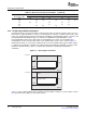
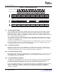
The 8-bit BT.656 mode uses three FIFOs for color separation. Samples are packed into each word as
shown in Figure 3-2 .
SPRUEM1 – May 2007 Video Capture Port 49
Submit Documentation Feedback