
Video Port/VCXO Interpolated Control (VIC) Port User's Guide

www.ti.com
3.3.4 Y/C FIFO Packing
Cr 9
Cr 1
Cb 9
Cb 1
Y 9
Y 1
Y 25
Y 17
Cb 5
Y 10
Little-Endian Packing
Cr 14
Cr 6
Y 0
Cb 0
Cb 14
Cb 6
Y 14
Y 6
Y 30
Y 22Y 23
Cr 15
Cr 7
Cb 15
Cb 7
Y 15
Y 7
Cr FIFO
Cb FIFO
63
Y FIFO
63
5556
5556
Y 31
63
VDIN[19−12]
5556
VCLKINA
VDIN[9−2]
Cr 11
Cr 3
Cb 11
Cb 3
Y 11
Y 3
Y 27
Y 19
Cr 2
Y 5
Y 20Y 21
Cr 13
Cr 5
40
40
Cb 13
Cb 5
Y 13
Y 5
4748
48 47
Cb 12
Cr 12
Cr 4
Cb 4
39 3231
Y 12
Y 4
39 3231
Cb 1
Y 29
40
Y 2
Cr 0
48 47
Y 1
Cb 2
Y 28
39
Cr 1
32 31
Y 4Y 3
Y 18
Cr 10
Cr 2
Cb 10
Cb 2
Y 10
Y 2
2324
2324
1516
1516
Y 26
Cr 3
Y 7
Cb 3
2324
Y 6
1516
Cb 4
Y 9Y 8
Y 16
Cr 8
Cr 0
0
Cb 8
Cb 0
0
Y 8
Y 0
78
8 7
Y 24
0
Cr 5
8 7
Y 11
Cb 4
3.4 BT.656 and Y/C Mode Field and Frame Operation
BT.656 and Y/C Mode Field and Frame Operation
For the Y/C video capture mode, the FIFO buffer is divided into three sections (three buffers). One section
is 2560 bytes deep and is dedicated for storage of Y data samples. The other two sections are dedicated
for storage of Cb and Cr data samples, respectively. The buffers for Cb and Cr samples are each 1280
bytes deep. The incoming video data stream is separated into Y, Cb, and Cr data streams, scaled (if
selected) and the Y, Cb, and Cr buffers are filled. Each of the three buffers has a memory-mapped
location associated with it; YSRC, CBSRC, and CRSRC. The YSRC, CBSRC, and CRSRC locations are
read only and are used by EDMAs to access video data samples stored in the FIFOs. Reads must always
be 64 bits.
If video capture is enabled, pixels in the capture window are captured in the Y, Cb, and Cr buffers. The
video capture module uses the YEVT, CbEVT, and CrEVT events to notify the EDMA controller to copy
data from the capture buffers to the DSP memory. The number of pixels required to generate the events is
set by the VCTHRLD n bits in VC xCTL (the VCTHRLD n value must be an even number for Y/C mode).
The capture module generates the events after VCTHRLD new pixels have been received. On every
YEVT, the EDMA should move data from the Y buffer to DSP memory using the YSRC register as the
source address. On every CbEVT, the EDMA should move data from the Cb buffer to DSP memory using
the CBSRC register as the source address. On every CrEVT, the EDMA should move data from the Cr
buffer to DSP memory using the CRSRC register as the source address. Note that transfer size from the
Cb and Cr buffers is half of the transfer size from the Y buffer since for every four Y samples, there are
two Cb and two Cr samples.
The three EDMA events are generated simultaneously when VCTHRLD is reached. Each event is
reenabled when the first read of the respective FIFO by the requested EDMA begins.
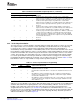
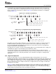
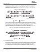
Captured data is always packed into 64 bits before being written into the capture FIFO(s). By default, data
is packed into the FIFO from right to left.
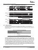
The 8-bit Y/C mode uses three FIFOs for color separation. Samples are packed into each word as shown
in Figure 3-3 .
Figure 3-3. 8-Bit Y/C FIFO Packing
Because EDMAs are used to transfer data from the capture FIFOs to memory, there is a large amount of
flexibility in the way that capture fields and frames are transferred and stored in memory. In some cases,
for example a EDMA structure can be created to provide a set of ping-pong or round-robin memory buffers
SPRUEM1 – May 2007 Video Capture Port 51
Submit Documentation Feedback