
Video Port/VCXO Interpolated Control (VIC) Port User's Guide

www.ti.com
3.4.2 Vertical Synchronization
BT.656 and Y/C Mode Field and Frame Operation
Table 3-6. BT.656 and Y/C Mode Capture Operation (continued)
VC xCTL Bit
CON FRAME CF2 CF1 Operation
1 0 0 1 Continuous field 1 capture. Capture only field 1. F1C is set after field 1
capture and causes CCMPx to be set (CCMPx interrupt can be disabled). The
video port continues capturing field 1 fields, regardless of the state of F1C.
1 0 1 0 Continuous field 2 capture. Capture only field 2. F2C is set after field 2
capture and causes CCMPx to be set (CCMPx interrupt can be disabled). The
video port continues capturing field 2 fields, regardless of the state of F2C.
1 0 1 1 Reserved
1 1 0 0 Continuous frame capture. Capture both fields. FRMC is set after field 2
capture and causes CCMPx to be set (CCMPx interrupt can be disabled). The
video port continues capturing frames, regardless of the state of FRMC.
1 1 0 1 Continuous progressive frame capture. Capture field 1. FRMC is set after field
1 capture and causes CCMPx to be set (CCMPx interrupt can be disabled).
The video port continues capturing frames, regardless of the state of FRMC.
(Functions identically to continuous field 1 capture mode except the FRMC bit
is used instead of the F1C bit.)
1 1 1 0 Reserved
1 1 1 1 Reserved
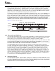
The video port uses a capture window to determine which incoming data samples to capture in each field.
The capture module uses a vertical line counter (VCOUNT) to track which video line is currently being
received. The line counter is compared to the appropriate capture window start (VCYSTART1 or
VCYSTART2) and stop (VCYSTOP1 or VCYSTOP2) values for the current field to determine if the current
line is within the capture window. In order to correctly align the capture window within the field, the capture
module must know which line should correspond to the first line of the field, that is, when to reset the line
counter. This point may vary depending on the type of capture being performed and the signals available
for vertical synchronization. The video port allows the vertical counter reset trigger to be determined by
programming the EXC and VRST bits in VC xCTL. The encoding of these bits is shown in Table 3-7 . Note
that VModes 2 and 3 are only available for single channel operation (channel A).
Table 3-7. Vertical Synchronization Programming
VC xCTL Bit
VMode EXC VRST Vertical Counter Reset Point
0 0 0 First EAV with V=1 after EAV with V=0 - beginning of vertical blanking period.
VCOUNT increments on each EAV.
1 0 1 First EAV with V=0 after EAV with V=1 - first active line. VCOUNT increments on each
EAV.
2 1 0 On HCOUNT reset after VCTL2 input active edge - beginning of vertical blanking or
vertical sync period. (VCTL2 must be configured as vertical control signal). VCOUNT
increments when HCOUNT is reset.
3 1 1 On HCOUNT reset after VCTL2 input inactive edge - end of vertical sync or first active
scan line. (VCTL2 must be configured as vertical control signal). VCOUNT increments
when HCOUNT is reset.
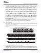
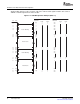
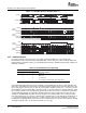
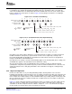
VMode 0 is used for BT.656 or Y/C capture (with embedded control) and corresponds to most digital video
standards that number lines beginning with the start of vertical blanking. VMode 1 can also be used for
BT.656 or Y/C capture but counts from the first active video line. This makes field detection more
straightforward in some instances (see Section 3.4.4 ) and allows the VCYSTART n bit to be set to 1, but
also has the effect of associating vertical blanking periods with the end of the previous field rather than the
beginning of the current field. (This could be an issue when capturing VBI data.) VCOUNT operation for
VMode 0 and VMode 1 is shown in Figure 3-4 .
SPRUEM1 – May 2007 Video Capture Port 53
Submit Documentation Feedback