
Video Port/VCXO Interpolated Control (VIC) Port User's Guide

www.ti.com
n
n
n
140
2
60
n
1440
Active Video
124
Y 2
Blanking Data
1
721
779
843
VCOUNT
VCOUNT
EXC=1
HRST=1
EXC=1
HRST=0
HCOUNT
720
HCOUNT
VCOUNT
0
AVID
EXC=1
HRST=0
EXC=1
HRST=1
HCOUNT
842
HCOUNT
VCOUNT
778
HSYNC
79
799
857
63
n−1
15
735722
2
736
n−1
16
793
857844
780
n−1
0
794
136
856855800
80 135
857 10
138137 139
56
12011964
0 55
121 123122
5857 59
Blanking
80.0
VCLKIN
VDIN[9−2]
80.0
10.0
10.0
80.0
80.0
10.0
10.0
10.0
80.0
80.0
10.0
10.0
80.0
10.0
80.0
Y 0
10.0
80.0
Cb 0
Cb 1
Y 1
Cr 0
n+1
1
721
779
843
720719718
857856 0
842842840
777776 778
722
2
844
780
10.0
Cb 0
80.0
Y 719
Cr 359
Y 718
10.0
80.0
10.0
80.0
276
3.4.4 Field Identification
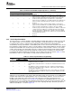
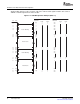
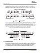
BT.656 and Y/C Mode Field and Frame Operation
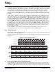
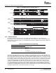
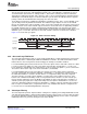
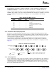
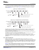
Figure 3-6. HCOUNT Operation Example (EXC = 1)
In order to properly synchronize to the source data stream and capture the correct fields, field
identification needs to be performed. Field identification is made using one of three methods: EAV, field
indicator input, or field detect logic. The field identification method is determined by the EXC, FLDD, and
FINV bits in VC xCTL.
Table 3-9. Field Identification Programming
VC xCTL Bit
EXC FLDD Field Detect Method
0 0 EAV code
0 1 EAV code
1 0 Use FID input
1 1 Use field detect (from HSYNC and VSYNC inputs)
In the BT.656 standard and in many Y/C standards, a field identification (F) bit is contained in EAV and
SAV codes embedded in the data stream. In the EAV field detect method, the F bit in the EAV of the first
line of every field is checked. If F = 0, then the current field is defined as field 1. If F = 1, then the current
field is defined as field 2. Depending on how the first line of a field is defined (as determined by the VRST
bit in VC xCTL) and the video stream being captured, the F value at the start of a field may not reflect the
actual field being supplied. The FINV bit in VC xCTL allows the detected field value to be inverted. (For
example, in BT.656 525/60 operation, the F bit changes to 0 to indicate field 1 on the fourth line of the
field. If the VRST bit is set so the line counter begins counting at line 1 of the field (the first EAV where V
is 1), then the F bit still indicates field 2 (F = 1) and needs to be inverted. If the VRST bit is set to start
counting lines beginning with the first active line (the first EAV where V is 0), the F value will have already
changed to indicate field 1 (F = 0) and no inversion is necessary.)
56 Video Capture Port SPRUEM1 – May 2007
Submit Documentation Feedback