
Video Port/VCXO Interpolated Control (VIC) Port User's Guide

www.ti.com
HSYNC#
(VCTL1)
VCLKIN
VSYNC#
(VCTL2)
64 Clocks
64 Clocks
3.4.5 Short and Long Field Detect
3.5 Video Input Filtering
Video Input Filtering
The field indicator method uses the FID input directly to determine the current field. This is useful for Y/C
data streams that do not have embedded EAV and SAV codes. The FID input is sampled at the start of
each field. If FID = 0, then field 1 is starting; if FID = 1, then field 2 is starting. The start of each field is
defined by the VRST bit in VC xCTL and is either the start or end of vertical blanking as determined by the
VBLNK input. The FINV bit may be used in this method in systems where the FID input has the opposite
polarity or where the field identification change lags the start of the field.
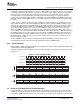
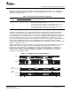
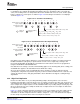
The field detect method uses HYSNC and VSYNC based field detect logic. This is used for BT.656 or Y/C
systems that provide only HSYNC and VSYNC. The field detect logic samples the state of the HSYNC
input on the VSYNC active edge. If HSYNC is active on the active VSYNC edge, then field 1 is detected; if
HSYNC is inactive on the active VSYNC edge, then field 2 is detected. Because of slight timing variations,
the VSYNC transition may not coincide exactly with the HSYNC transition. The detection logic should
implement a ± 64 clock detection window around HSYNC. If both HSYNC and VSYNC leading edges occur
within 64 cycles of each other, then field 1 is detected; otherwise, field 2 is assumed. This is shown in
Figure 3-7 for active-low sync signals.
Figure 3-7. Field 1 Detection Timing
The short and long field detect logic is used to notify the DSP when a captured field shorter or longer than
expected. Detection is enabled by the SFDE and LFDE bits in VC xCTL. The SFD and LFD bits in VPIS
indicate when a short or long field occurred and trigger an interrupt to the DSP if enabled.
If a vertical blanking period is detected before the end of the capture field, a short field is detected . If EAV
is used for vertical sync (EXC = 0), then a short field is detected when an EAV with V = 1 occurs on or
before VCOUNT = VCYSTOP n. If the VCTL2 input is used for vertical sync (EXC = 1), then a short field is
detected if a VCTL2 active edge occurs before VCOUNT = (VCYSTOP n).
If a vertical blanking period occurs more than 1 line past the end of the capture field, a long field is
detected. A long field is detected when VCOUNT = VCYSTOP n + 1. (A long field is only detected when
the VRST bit in VC xCTL is cleared to 0; when VRST = 1, a long field is always detected.) Long field
detection cannot be used if the capture window is a vertical subset of the field that crops lines at the
bottom. Such a window would always result in a long field detection. If VCTL2 is used for vertical sync,
then the VCTL2 signal must represent VBLNK (vertical blank) for proper long field detect. If VCTL2 is a
VSYNC (vertical sync) input, then a long field is always detected. (Even if VCYSTOP n is set to the last
active line, VCOUNT usually increments past VCYSTOP n + 1 while it counts the vertical front porch lines
that occur prior to VSYNC active.) Long field detection is only available when VRST is configured to be
reset at the start of vertical blanking(VRST=0 in VCX_CTL).
The video input filter performs simple hardware scaling and re-sampling on incoming 8-bit BT.656 or 8-bit
Y/C data. Filtering hardware is always disabled during raw data capture modes. For proper filter operation,
the channel's EXC bit in VC xCTL must be cleared to 0 (embedded timing reference codes used) and the
CAPEN input must not go inactive during the active video window.
SPRUEM1 – May 2007 Video Capture Port 57
Submit Documentation Feedback