
Video Port/VCXO Interpolated Control (VIC) Port User's Guide

www.ti.com
YCbCr 4:2:2 co-sited
input samples
1/2 scaled co-sited
capture results
Luma (Y)
sample
Y’
h
= (-3Y
e
+ 32Y
g
+ 70Y
h
+ 32Y
i
- 3Y
k
) / 128
-
Chroma (Cb/Cr)
samples
-
a b c d e f g h i j k l
Y’
f
= (-3Y
c
+ 32Y
e
+ 70Y
f
+ 32Y
g
- 3Y
i
) / 128
Cb’
f
= (-1Cb
c
+ 17Cb
e
+ 17Cb
g
- 1Cb
i
) / 32
Cr’
f
= (-1Cr
c
+ 17Cr
e
+ 17Cr
g
- 1Cr
i
) / 32
Y’
g
= (-3Y
d
+ 32Y
f
+ 70Y
g
+ 32Y
h
-3Y
j
) / 128
Cb’
f
= (-1Cb
c
+ 17Cb
e
+ 17Cb
g
- 1Cb
i
) / 32
Cr’
f
= (-1Cr
c
+ 17Cr
e
+ 17Cr
g
- 1Cr
i
) / 32
YCbCr 4:2:2 co-sited
input samples
1/2 scaled
chroma-resampled
capture results
Luma (Y)
sample
-
Chroma (Cb/Cr)
samples
-
a b c d e f g h i
j
k l
3.5.4 Edge Pixel Replication
Video Input Filtering
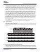
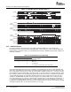
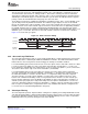
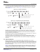
The filtering for the luminance portion of the scaling filter changes depending on if chrominance
re-sampling is also enabled. (By changing the luminance filter, the chrominance filters can remain the
same.) The resulting values are clamped to between 01h and FEh and sent to the Y, Cb, and Cr capture
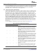
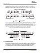
buffers. Scaling for co-sited capture is shown in Figure 3-9 and scaling for chrominance re-sampling is
shown in Figure 3-10 .
Figure 3-9. 1/2 Scaled Co-Sited Filtering
Figure 3-10. 1/2 Scaled Chrominance Re-sampled Filtering
Note that because input scaling is limited to 1/2, true CIF horizontal resolution is not achieved if the full
BT.656 horizontal line (720 pixels) is captured. A CIF size line can be captured by selecting a 704
pixel-sized window within the BT.656 line. This window size and location on the line are programmed
using the VCXSTART n and VCXSTOP n bits.
Note that when 1/2 scaling is selected, horizontal timing applies to the incoming data (before scaling). The
VCTHRLD value applies to the data written into the FIFO after scaling.
Also note when using the scalar, standard BT.601 values should be used for the luma and chroma
(16-240) data. Using values beyond this range may result in overflow and underflow. The scalar does not
saturate the data; therefore, data going below 00h or above FFh will not be clipped, resulting in image
degradation.
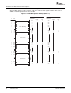
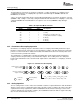
Because the filters make use of preceding and trailing samples, filtering artifacts can occur at the
beginning of the BT.656 or Y/C active line because no samples exist before the SAV code, and at the end
of the BT.656 active line because no samples exist after the EAV code. In order to minimize artifacts, the
first m samples after sample 0 (where m is the maximum number of preceding samples used by any of the
filters) are mirrored to the left of sample 0 and the last m samples before the last sample are mirrored to
the right of the last sample.
Figure 3-11 shows edge pixel replication assuming an m value of 3. Sample a is the first sample after the
SAV code. Therefore, samples b-d are mirrored to the left of sample a to provide values for the filter
calculations on the first few pixels in the line. Likewise, samples n - 1 to n - 3 are mirrored to the right of
the last sample n to provide values for the last few pixels on the line.
SPRUEM1 – May 2007 Video Capture Port 59
Submit Documentation Feedback