
Video Port/VCXO Interpolated Control (VIC) Port User's Guide


www.ti.com
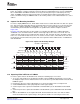
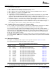
PACSTRT
VCLKIN
CAPEN
VDIN[9:2] Sync Byte Byte 1 Byte 2 Byte 3 Byte 4
Start Capture
3.8.3 TCI Capture Error Detection
3.8.4 Synchronizing the System Clock
TCI Capture Mode
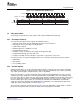
Figure 3-15. Parallel TCI Capture
The video port checks for two types of errors during TCI capture. The first is a packet error on the
incoming packet as indicated by an active PACERR signal. If PACERR is active during any of the first
eight bytes of a packet and error packet filtering is enabled (ERRFILT bit in TCICTL is set), then the video
port will ignore (not capture) the incoming data until the next PACSTRT is received. If error packet filtering
is not enabled or if PACERR becomes active sometime after the first eight bytes of the packet, the entire
packet is captured and the PERR bit is set in the timestamp inserted at the end of the packet.
The second error detected is an early PACSTRT error. This occurs when an active PACSTRT is detected
before an entire packet (as determined by the packet size programmed in VCASTOP) has been captured.
The port will continue to capture the expected packet size but will set the PSTERR bit in the timestamp
inserted at the end of the packet. After capture completion, the port will wait for a subsequent PACSTRT
before beginning capture of another packet.
Note: When you are using TCI capture mode, you must clock the STCLK input. If you do not
need to synchronize to the system clock, you should clock STCLK via the VPxCLK0 input.
Synchronization is an important aspect of decoding and presenting data in real-time digital data delivery
systems. This is addressed in MPEG-2 transport packets by transmitting timing information in the
adaptation fields of selected data packets. This value serves as a reference for timing comparison in the
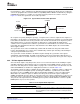
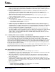
receiving system. The program clock reference (PCR) header, shown in Figure 3-16 , is a 48-bit field (six
bits are reserved). A 42-bit value is transmitted within the 48-bit stream and consists of a 33-bit PCR field
that represents a 90-kHz clock sample and a 9-bit PCR extension field that represents a 27-MHz clock
sample. The PCR indicates the expected time at the completion of reading the field from the bit stream at
the transport decoder. The transport data packets are in-sync with the encoder time clock.
Figure 3-16. Program Clock Reference (PCR) Header Format
47 15 14 9 8 0
PCR Reserved PCR extension
The video port, in conjunction with the VCXO interpolated control (VIC), allows a combined hardware and
software solution to synchronize the local system time clock (STC) with the encoder time clock reference
transmitted in the bit stream.
The video port maintains a hardware counter that counts the system time. The counter is driven by a
system time clock (STCLK) input driven by an external VCXO. The counter is split into two fields: a 33-bit
field (PCR base) that counts at 90 kHz and a 9-bit field (PCR extension) that counts at 27 MHz. The 9-bit
64 Video Capture Port SPRUEM1 – May 2007
Submit Documentation Feedback