
Video Port/VCXO Interpolated Control (VIC) Port User's Guide


www.ti.com
27 MHz
Modulo 300
Counter 233
PCR Extension
PCR Base
CTMODE
0
1
STCLK
90 kHz
External VCXO
3.8.5 TCI Data Capture Notification
TCI Capture Mode
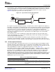
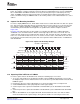
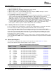
counter counts from 0 to 299 at 27 MHz. Each time the 9-bit counter rolls over to 0, the 33-bit counter is
incremented by 1. This is equivalent to the PCR timestamp transmitted in the bit-stream. The 33-bit field
can also be programmed to count at 27 MHz for compatibility with the MPEG-1 32-bit PCR, by setting the
CTMODE bit in VCCTL to 1; in which case, the PCR extension portion of the counter is not used.
Figure 3-17 shows the system time clock counter operation.
Figure 3-17. System Time Clock Counter Operation
On reception of a packet (during the sync byte), a snapshot of the counter is captured. This snapshot, or
timestamp, is inserted in the receiving FIFO at the end of each data packet. Software uses this timestamp,
to determine the deviation of the local system time clock from the encoder time clock. Any time a packet
with a PCR header is received, the timestamp for that packet is compared with the PCR value by
software. A PLL is implemented in software to synchronize the STCLK with the encoder time clock value
in the PCR. This algorithm then drives the VIC, which drives the VDAC output to the external VCXO,
which supplies STCLK.
The system time clock counter is initialized by software with the PCR of the first packet with a PCR
header. After initialization, the counter can be reinitialized by software upon detecting a discontinuity in
subsequent packet PCR header values.
The system time is made available to the DSP at any time through the system time clock registers
(TCISTCLKL and TCISTCLKM). The DSP can program the video port to interrupt the DSP whenever a
specific system time is reached or whenever a specific number of system time clock cycles have elapsed.
Since TCI mode captures only data packets, there is no need for field control. Some flexibility in capture
and DSP notification is still provided in order to accommodate various EDMA structures and processing
flows. Each TCI data packet is treated similar to a progressive scan video frame. The TCI mode uses the
CON and FRAME bits of VCACTL in a slightly different manner, as listed in Table 3-12 .
The CON bit controls the capture of multiple packets. When CON = 1, continuous capture is enabled, the
video port captures incoming data packets (assuming the VCEN bit is set) without the need for DSP
interaction. It relies on a EDMA structure with circular buffering capability to service the capture FIFO.
When CON = 0, continuous capture is disabled, the video port sets the frame capture complete bit
(FRMC) in VCASTAT upon the capture of each packet. Once the capture complete bit is set, at most, one
more frame can be received before capture operation is halted (as determined by the FRAME bit state).
This prevents subsequent data from overwriting previous packets until the DSP has a chance to update
EDMA pointers or process those packets.
Table 3-12. TCI Capture Mode Operation
VCACTL Bit
CON FRAME CF2 CF1 Operation
0 0 x x Noncontinuous packet capture. FRMC is set after packet capture and causes
CCMPA to be set. Capture will halt upon completion of the next data packet
unless the FRMC bit is cleared. (DSP has the entire next data packet time to
clear FRMC.)
SPRUEM1 – May 2007 Video Capture Port 65
Submit Documentation Feedback