
Video Port/VCXO Interpolated Control (VIC) Port User's Guide


www.ti.com
3.12.1 Handling FIFO Overrun Condition in TCI Capture Mode
3.13 Video Capture Registers
Video Capture Registers
5. Write to TCISTCMPL, TCISTCMPM, TCISTMSKL, and TCISTMSKM if needed to initiate an interrupt,
based on STC absolute time.
6. Write to TCITICKS if an interrupt is desired every x cycles of STC.
7. Write to VPCTL to select TCI capture operation (TCI = 1).
8. Write to VPIE to enable overrun (COVRA) and capture complete (CCMPA) interrupts, if desired.
9. Write to VCACTL to set capture mode (CMODE = 010).
10. Set VCEN bit in VCACTL to enable capture.
11. Capture begins on the first VCLKINA rising edge when CAPENA and PACSTRT are valid. A EDMA
event is generated as triggered by VCATHRLD1. When the entire packet has been captured
(DCOUNT = VCYSTOP and VCXSTOP combined value), the FRMC bit in VCASTAT is set causing the
CCMP x bit in VPIS to be set. This generates a DSP interrupt, if CCMP x is enabled in VPIE.
12. If continuous capture is enabled, the video port begins capturing again on the next VCLKIN rising
edge when CAPEN and PACSTRT are valid. If noncontinuous capture is enabled, the next data packet
is captured during which the DSP must clear the FRMC bit or further capture is disabled. If single
frame capture is enabled, capture is disabled until the DSP clears the FRMC bit.
In case of a FIFO overrun, the COVR x bit is set in VPIS. This condition initiates an interrupt to the DSP, if
the overrun interrupt is enabled (setting the COVR x bit in VPIE enables overrun interrupt).
The overrun interrupt routine should set the BLKCAP bit in VC xCTL and it should reconfigure EDMA
channel settings. The EDMA channel must be reconfigured for capture of the next frame since the current
frame transfer failed. Setting the BLKCAP bit flushes the capture FIFO and blocks EDMA events for the
channel. As long as the BLKCAP bit is set, the video capture channel ignores the incoming data but the
internal data counter continues counting.
The BLKCAP bit should be cleared to 0 in order to continue capture. Clearing the BLKCAP bit takes effect
on the next PACSTRT. (EDMA events are still going to be blocked in the TCI packet in which the BLKCAP
bit is cleared.)
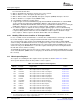
The registers for controlling the video capture mode of operation are listed in Table 3-13 . See the
device-specific datasheet for the memory address of these registers.
Table 3-13. Video Capture Control Registers
Offset
Address
(1)
Acronym Register Name Section
100h VCASTAT Video Capture Channel A Status Register Section 3.13.1
104h VCACTL Video Capture Channel A Control Register Section 3.13.2
108h VCASTRT1 Video Capture Channel A Field 1 Start Register Section 3.13.3
10Ch VCASTOP1 Video Capture Channel A Field 1 Stop Register Section 3.13.4
110h VCASTRT2 Video Capture Channel A Field 2 Start Register Section 3.13.5
114h VCASTOP2 Video Capture Channel A Field 2 Stop Register Section 3.13.6
118h VCAVINT Video Capture Channel A Vertical Interrupt Register Section 3.13.7
11Ch VCATHRLD Video Capture Channel A Threshold Register Section 3.13.8
120h VCAEVTCT Video Capture Channel A Event Count Register Section 3.13.9
140h VCBSTAT Video Capture Channel B Status Register Section 3.13.1
144h VCBCTL Video Capture Channel B Control Register Section 3.13.10
148h VCBSTRT1 Video Capture Channel B Field 1 Start Register Section 3.13.3
14Ch VCBSTOP1 Video Capture Channel B Field 1 Stop Register Section 3.13.4
150h VCBSTRT2 Video Capture Channel B Field 2 Start Register Section 3.13.5
(1)
The absolute address of the registers is device/port specific and is equal to the base address + offset address. See the
device-specific datasheet to verify the register addresses.
70 Video Capture Port SPRUEM1 – May 2007
Submit Documentation Feedback