
Video Port/VCXO Interpolated Control (VIC) Port User's Guide

www.ti.com
3.13.1 Video Capture Channel x Status Register (VCASTAT, VCBSTAT)
Video Capture Registers
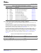
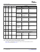
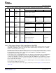
Table 3-13. Video Capture Control Registers (continued)
Offset
Address
(1)
Acronym Register Name Section
154h VCBSTOP2 Video Capture Channel B Field 2 Stop Register Section 3.13.6
158h VCBVINT Video Capture Channel B Vertical Interrupt Register Section 3.13.7
15Ch VCBTHRLD Video Capture Channel B Threshold Register Section 3.13.8
160h VCBEVTCT Video Capture Channel B Event Count Register Section 3.13.9
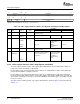
180h TCICTL TCI Capture Control Register Section 3.13.11
184h TCICLKINITL TCI Clock Initialization LSB Register Section 3.13.12
188h TCICLKINITM TCI Clock Initialization MSB Register Section 3.13.13
18Ch TCISTCLKL TCI System Time Clock LSB Register Section 3.13.14
190h TCISTCLKM TCI System Time Clock MSB Register Section 3.13.15
194h TCISTCMPL TCI System Time Clock Compare LSB Register Section 3.13.16
198h TCISTCMPM TCI System Time Clock Compare MSB Register Section 3.13.17
19Ch TCISTMSKL TCI System Time Clock Compare Mask LSB Register Section 3.13.18
1A0h TCISTMSKM TCI System Time Clock Compare Mask MSB Register Section 3.13.19
1A4h TCITICKS TCI System Time Clock Ticks Interrupt Register Section 3.13.20
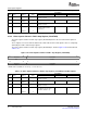
The video capture channel x status register (VCASTAT, VCBSTAT) indicates the current status of the
video capture channel.
In BT.656 capture mode, the VCXPOS and VCYPOS bits indicate the HCOUNT and VCOUNT values,
respectively, to track the coordinates of the most recently received pixel. The F1C, F2C, and FRMC bits
indicate completion of fields or frames and may need to be cleared by the DSP for capture to continue,
depending on the selected frame capture operation (see Section 3.4.1 ).
In raw data and TCI modes, the VCXPOS and VCYPOS bits reflect the lower and upper 12 bits,
respectively, of the 24-bit data counter that tracks the number of received data samples. The FRMC bit
indicates when an entire data packet has been received and may need to be cleared by the DSP for
capture to continue, depending on the selected frame operation (see Section 3.7.1 and Section 3.8.5 ).
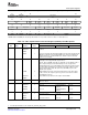
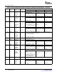
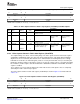
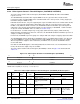
The video capture channel x status register (VC xSTAT) is shown in Figure 3-21 and described in
Table 3-14 .
Figure 3-21. Video Capture Channel x Status Register (VCxSTAT)
31 30 29 28 27 16
FSYNC FRMC F2C F1C VCYPOS
R-0 R/WC-0 R/WC-0 R/WC-0 R-0
15 13 12 11 0
Reserved VCFLD VCXPOS
R-0 R-0 R-0
LEGEND: R = Read only; WC = Write 1 to clear, a write of 0 has no effect; - n = value after reset
SPRUEM1 – May 2007 Video Capture Port 71
Submit Documentation Feedback