
Video Port/VCXO Interpolated Control (VIC) Port User's Guide

www.ti.com
3.13.4 Video Capture Channel x Field 1 Stop Register (VCxSTOP1)
Video Capture Registers
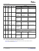
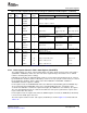
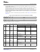
Figure 3-23. Video Capture Channel x Field 1 Start Register (VCxSTRT1)
31 28 27 16
Reserved VCYSTART
R-0 R/W-0
15 14 12 11 0
SSE Reserved VCXSTART/VCVBLNKP
R/W-1 R-0 R/W-0
LEGEND: R/W = Read/Write; R = Read only; - n = value after reset
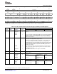
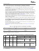
Table 3-16. Video Capture Channel x Field 1 Start Register (VCxSTRT1) Field Descriptions
Description
Bit field
(1)
symval
(1)
Value BT.656 or Y/C Mode Raw Data Mode TCI Mode
31-28 Reserved - 0 Reserved. The reserved bit location is always read as 0. A value written to this
field has no effect.
27-16 VCYSTART OF( value) 0-FFFh Starting line number. Not used. Not used.
DEFAULT 0
15 SSE OF( value) Startup synchronization enable bit.
DISABLE 0 Not used. Startup Not used.
synchronization is
disabled.
DEFAULT 1 Not used. Startup Not used.
synchronization is
ENABLE
enabled.
14-12 Reserved - 0 Reserved. The reserved bit location is always read as 0. A value written to this
field has no effect.
11-0 VCXSTART OF( value) 0-FFFh VCXSTART bits define the VCVBLNKP bits define Not used.
starting pixel number. Must be the minimum CAPEN
VCVBLNKP
an even number (LSB is inactive time to be
treated as 0). interpreted as a
vertical blanking
period.
DEFAULT 0
(1)
For CSL implementation, use the notation VP_VC xSTRT1_ field_ symval
The video capture channel x field 1 stop register (VCxSTOP1) defines the end of the field 1-captured
image or the end of the raw data or TCI packet.
In raw capture mode, the horizontal and vertical counters are combined into a single counter that keeps
track of the total number of samples received.
In TCI capture mode, the horizontal and vertical counters are combined into a single data counter that
keeps track of the total number of bytes received. The capture starts when a SYNC byte is detected. The
data counter counts bytes as they are received. The FRMC bit (in VC xSTAT) gets set each time a packet
has been received.
The video capture channel x field 1 stop register (VC xSTOP1) is shown in Figure 3-24 and described in
Table 3-17 .
Video Capture Port76 SPRUEM1 – May 2007
Submit Documentation Feedback